




Lubrication system
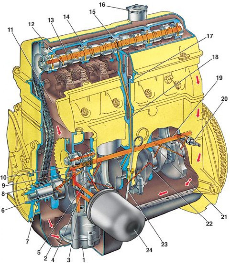
1 – oil pump; 2 – oil pan; 3 – oil supply channel from the pump to the filter; 4 – horizontal channel for supplying oil from the filter to the oil line; 5 – channel for supplying oil to the gear of the oil pump drive and ignition distributor; 6 – channel in the crankshaft journal; 7 – front crankshaft oil seal; 8 – oil supply channel from the oil line to the main bearing and to the drive shaft of the oil pump and ignition distributor; 9 – gear for driving the oil pump and ignition distributor; 10 – oil pump and ignition distributor drive shaft; 11 – oil drain channel; 12 – channel in the camshaft cam; 13 – main channel in the camshaft; 14 – channel in the bearing journal of the camshaft; 15 – annular groove on the middle bearing journal of the camshaft; 16 – oil filler cap; 17 – inclined channel in the cylinder head; 18 – vertical channel in the cylinder block; 19 – oil line; 20 – Oil pressure indicator lamp sensor; 21 – oil supply channel to the main bearing; 22 – oil supply channel from the main bearing to the connecting rod; 23 – oil level indicator; 24 – oil filter
The lubrication system is combined. The main and connecting rod bearings, the supports and cams of the camshaft, the bearings of the shaft 10 and the gear 9 of the drive of the oil pump 1 and the ignition distributor are lubricated under pressure. The oil flowing out of the gaps and splashed by the moving parts lubricates the cylinder walls, pistons with piston rings, piston pins in the piston bosses, the camshaft drive chain, the supports of the valve drive levers, as well as the valve stems in their guide bushings.
When the oil pressure drops below the permissible level, the low oil pressure indicator lamp lights up.
The gear type oil pump is installed inside the crankcase and is attached to the cylinder block with two bolts.
The oil filter is full-flow, non-separable, with bypass and anti-drain valves.