
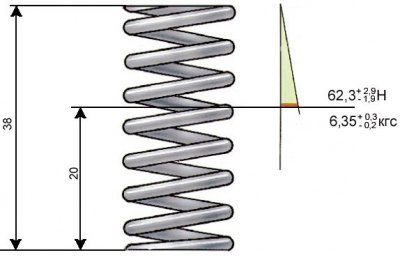
Basic data for checking the pressure reducing valve spring
1. After dismantling, wash all pump parts with kerosene or gasoline, blow with compressed air, and then inspect the pump housing and cover; Replace parts if cracked.
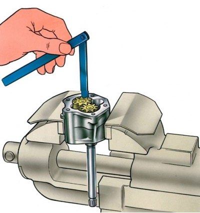
2. Check with a set of feelers the gaps between the teeth of the gears, as well as between the outer diameters of the gears and the walls of the pump housing, which should be 0.15 mm, respectively (maximum allowable 0.25 mm) and 0.11 - 0.18 mm (maximum allowable 0.25 mm).
3. If the clearances exceed the limits, then replace the gears, and if necessary, the pump housing.
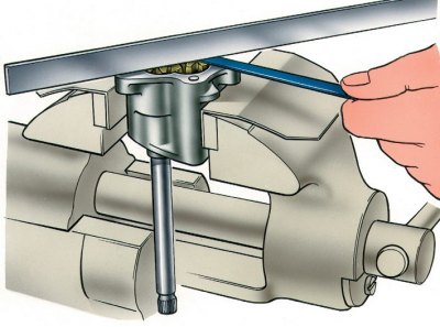
4. Using a feeler gauge and a ruler, check the gap between the ends of the gears and the plane of the housing, which should be equal to 0.066–0.161 mm (maximum allowable 0.2 mm). If the clearance is greater than 0.2 mm, replace the gears or pump housing, whichever is worn.
5. After measuring the parts, determine the gap between the driven gear and its axis, which should be 0.017–0.057 mm (maximum allowable 0.1 mm), as well as between the pump shaft and the hole in the housing, this gap should be 0.016–0.055 mm (maximum allowable 0.1 mm). If the clearances are out of range, replace the worn parts.
Checking the pressure reducing valve
6. When repairing the oil pump, check the pressure reducing valve. Pay attention to the surfaces of the valve and pump, as possible contamination or deposits on the mating surfaces can lead to seizing. The mating surface of the valve must be free of nicks and burrs that could reduce system pressure.
7. Check up elasticity of a spring of the reducing valve, comparing the received data with resulted on fig. Basic data for checking the pressure reducing valve spring.
Checking the roller and gears of the oil pump drive
8. There should be no dents or scratches on the surfaces of the bearing necks of the roller and on the working surface of the eccentric.
9. On the teeth of the gears of the oil pump drive and the ignition distributor, chipping is not allowed, with such a defect, replace the roller and gear.
Checking the bushings of the oil pump drive shaft
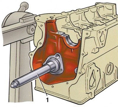
10. Check the inner diameter of the bushings, their pressing into the sockets, as well as the coincidence of the lubrication hole in the front bushing with the channel in the cylinder block (turning the sleeve). The inner surface must be smooth and free of burrs.
11. By measuring the diameters of the roller and bushings, determine the gaps between the bushings and the bearing surfaces of the roller. If the gap exceeds 0.15mm (wear limit), and also in case of damage to the surfaces of the bushings or weakening of their pressing, replace the bushings.
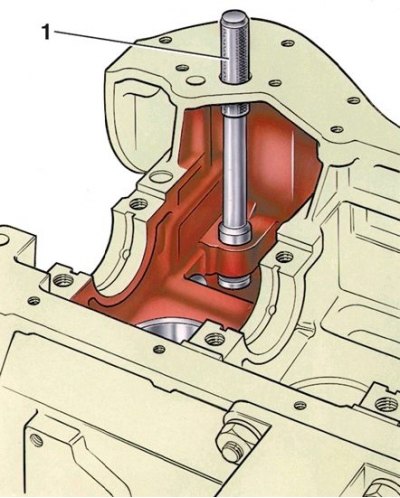
12. When replacing, use tool A.60333/1/2 both for removal and installation (1 - mandrel А.60333/1/2).
13. The bushings must be pressed into their sockets with the oil hole in the front bushing facing the bore in the cylinder block.
14. After pressing in, the bushings must be finished and finished to the inside diameter (dimensions are given in fig. The main dimensions of the oil pump and its drive).
15. To ensure complete alignment of the shaft bushings, a reamer A.90353 is used to finish them, which simultaneously processes both bushings.
Checking the bushing of the oil pump drive gear
16. The inner surface must be smooth and without scoring, otherwise replace the bushing.
17. Use tool A.60326/R to press out and press in the bushing (1 - mandrel А.60326/R).
18. After pressing the sleeve, expand to a diameter of 16.016–16.037 mm.