

Open large image in new tab »
Pic. eleven: 1. Carburetor heating block. 2. Throttle valve of the first chamber. 3. Branch pipe for suction of crankcase gases. 4. Lever drive accelerator pump. 5. Accelerator pump drive cam. 6. Accelerator pump diaphragm. 7. fuel jet economizer power modes. 8. Carburetor body. 9. Economizer diaphragm power modes. 10. Solenoid shut-off valve. 11. Fuel jet idling. 12. Carburetor cover. 13. Fuel supply pipe. 14. The main air jet of the first chamber. 15. Air damper. 16. Accelerator pump nozzles with fuel supply valve. 17. Diaphragm of the starting device. 18. Trigger adjustment screw. 19. Adjusting screw for the amount of idle mixture. 20. Second chamber lock lever. 21. Branch pipe connected to the vacuum regulator of the ignition distributor. 22. Adjusting screw for the quality of the idle mixture. 23. Throttle actuator lever. 24. Adjusting screw for slightly opening the throttle valve of the first chamber. 25. Choke control lever. 26. The rod of the starting device. 27. Electrical wire for the forced idle economizer limit switch. 28. Choke lever. 29. The main air jet of the second chamber. 30. Emulsion tube of the second chamber. 31. Small diffuser of the main dosing system of the second chamber. 32. Fuel filter. 33. Float chamber needle valve. 34. Throttle valve of the second chamber. 35. Throttle lever of the second chamber. 36. The main fuel jet of the second chamber. 37. Throttle actuator lever of the second chamber. 38. Float.
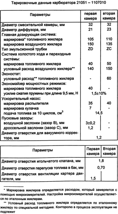
On cars VAZ-2105 and VAZ-2104 from 1985-87. carburetors model 21051-1107010 are installed. Calibration data for the carburetor are shown in the table.
The carburetor has a balanced float chamber, a crankcase exhaust system for the throttle valve, and a blocking of the second chamber. The carburetor has two main metering systems of the first and second chambers, an idle system of the first chamber with a transition system, a transition system of the second chamber, a forced idle economizer, a power mode economizer, an econostat, a mechanically driven diaphragm accelerator pump and a diaphragm starter. Since 1988, econostat has not been installed on carburetors 21051-1107010.
The carburetor consists of two body parts: body 8 and cover 12 of the carburetor. The cover is sealed with a gasket and screwed to the housing. In the carburetor cover there are inlet mouths of the first and second chambers, wells for supplying air to the main air jets, balancing holes connecting the float chamber with the cavity behind the air filter filter element. The air filter housing is installed on four studs screwed into cover 12. In the inlet neck of the first chamber, an air damper 15 of the starting device is installed. A lever 28 with two pins is rigidly mounted on the axis of the air damper, one of which is fitted with a return spring. The second pin enters the shaped groove of the lever 25 of the air damper control. Lever 25 is mounted freely on an axle wrapped in cover 12. A bushing is fixed on lever 25, to which the air damper actuator rod is attached with a screw. The adjusting screw 24 for slightly opening the throttle valve of the first chamber and the pin of the lever 20 for blocking the second chamber rest on the outer edge of the lever 25.
In the cover 12 of the carburetor, a needle shut-off valve 33 for the fuel supply, a float 38, a fuel filter 32, a pipe 13 for supplying fuel to the float chamber are installed. To the tide of the cover 12, four screws fasten the cover of the starting device with a diaphragm 17, assembled with a rod 26. The channels of the econostat, the transition system of the second chamber, the idle system, the starting device are made in the carburetor cover. The solenoid shut-off valve 10 with an idle fuel jet is wrapped in the cover.
The required fuel level in the float chamber is ensured by the correct installation of serviceable elements of the locking device. The correct installation of the float 38 is checked by a gauge, which is installed perpendicular to the cover 12, which is held horizontally with the floats up. There must be a gap of no more than 1 mm between the floats and the gauge along the contour.
When adjusting the level, it is necessary to make sure that the weight of the float 38 assembled with the lever is no more than 6.23 g, the float must not be damaged and rotate freely on the axis.
Adjust by bending the tongue and float levers. The bearing surface of the tongue must be perpendicular to the axis of the needle valve 33 and free of dents and nicks.
Large diffusers are cast in the carburetor body 8, small easily removable diffusers 31 are installed, cast integrally with the sprayers of the main dosing systems. In the housing there are channels of the main dosing systems, an idle system, a transition system of the second chamber, an economizer of power modes, an accelerator pump and a continuation of the channel of the starting device into the throttle space of the carburetor. In the case 8, there are also nozzles 16 of the accelerator pump with a ball valve, main air jets 14 and 29 with emulsion tubes 30 in emulsion wells, an intake tube of the transition system with a fuel jet. The main fuel jets 36 are wrapped in the emulsion wells. The pipe 21 for supplying the hose of the vacuum ignition timing regulator and the pipe 3 for exhausting crankcase gases are pressed into the carburetor body, which is connected by channels and a calibrated hole with a diameter of 1.5 mm with a cavity behind the throttle valves. The calibrated hole does not have a noticeable effect on the depletion of the combustible mixture with closed throttle valves at idle. In the tides of the carburetor body, an adjusting screw for the completeness of closing the throttle valve 34 of the second chamber, as well as an adjusting screw 19 for the amount of idle mixture with an electric drive 27 of the economizer limit switch for forced idling, are installed. An adjusting screw 22 of the quality of the idle mixture is wrapped in the body, the block 1 of the carburetor heating is fastened with a screw in the throttle zone of the first chamber, through which the coolant of the engine cooling system passes.
To the tide of the housing 8, which forms the working cavity of the accelerator pump, the cover of the accelerator pump is attached with four screws, with the lever 4 of the drive assembly with the diaphragm 6 of the pump. The cover of the power mode economizer with a working diaphragm 9 is also fastened to the body with screws. A spring acts on the diaphragm. A fuel jet 7 and an economizer valve for power modes are installed in the carburetor body under the diaphragm 9.
In the lower part of the housing 8, throttle valves 2 and 34 of the first and second chambers are installed on the axes. On the axis of the throttle valve of the first chamber are installed: lever 23 of the throttle actuator with an adjusting screw 24 for slightly opening the throttle valve of the first chamber and with a lever 20 for blocking the second chamber; the lever 37 of the throttle actuator of the second chamber; return spring and cam 5 of the accelerator pump. Throttle lever 35 is mounted on the throttle valve axis of the second chamber.
Blocking of the second chamber does not allow the opening of the throttle valve of the second chamber in any mode of engine operation, if the air damper is not fully open. The blocking excludes the operation of the second mixing chamber when the engine is cold. The lock lever 20 is pivotally mounted on the throttle actuator lever 23.
The idle speed of the engine is adjusted by adjusting screws: screw 19 of the amount of the mixture, which regulates the amount of opening of the throttle valve of the first chamber, and screw 22 of the composition (quality) mixtures. After adjustment, the adjusting screw 22 is closed with a plastic plug.