




Open large image in new tab »
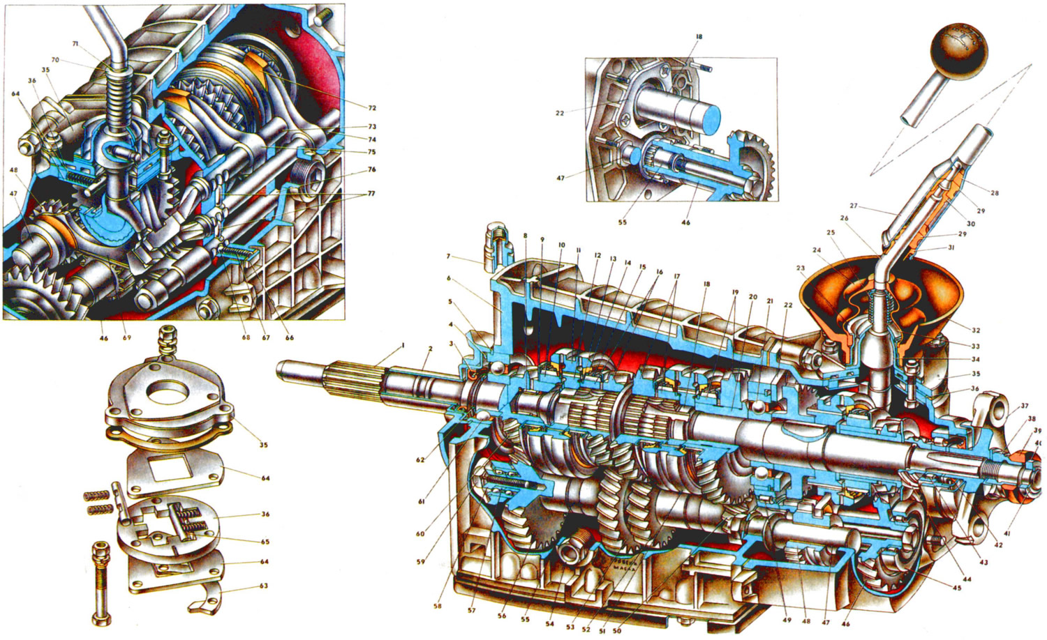
Fig. 18. Five-speed gearbox: 1. Primary shaft. 2. Gearbox front cover. 3. Primary shaft oil seal. 4. Spring washer. 5. Bearing mounting ring. 6. Gearbox housing. 7. Breather. 8. Secondary shaft needle bearing. 9. Synchronizer spring thrust washer. 10. Fourth gear synchronizer ring. 11. Third and fourth gear synchronizer sliding sleeve. 12. Third and fourth gear synchronizer sleeve hub. 13. Synchronizer retaining ring. 14. Synchronizer blocking ring. 15. Synchronizer spring. 16. Third gear synchronizer ring and gear ring. 17. Secondary shaft synchronizer ring and gear ring. 19. 1st gear synchronizer pinion and ring gear. 20. 1st gear pinion sleeve. 21. Secondary shaft intermediate bearing. 22. Intermediate bearing retaining plate. 23. Flange. 24. Protective boot. 25. Spring. 26. Gear shift lever. 27. Gear shift lever rod. 28. Elastic damper pad. 29. Rubber damper bushing. 30. Damper spacer sleeve. 31. Damper locking sleeve. 32. Sleeve. 33. Spherical washer. 34. Lever ball joint. 35. Gear shift lever housing. 36. Guide plate. 37. Flange of elastic cardan transmission coupling. 38. Nut. 39. Centering ring seal. 40. Centering ring. 41. Retaining ring. 42. Secondary shaft rear bearing oil seal. 43. Secondary shaft rear bearing. 44. Speedometer drive pinion. 45. Gear block bearing. 46. 5th and reverse gear gear block. 47. Reverse intermediate gear shaft shaft. 48. Reverse intermediate gear. 49. Intermediate shaft rear bearing. 50. 1st gear pinion of intermediate shaft. 51. 1st and 2nd gear synchronizer sliding sleeve. 52. 2nd gear pinion of intermediate shaft. 53. 3rd gear pinion of intermediate shaft. 54. Filler and inspection hole plug. 55. Intermediate shaft. 56. Intermediate shaft constant mesh gear. 57. Intermediate shaft front bearing. 58. Intermediate shaft bearing clamp washer. 59. Clamp washer bolt. 60. Input shaft constant mesh gear. 61. Input shaft rear bearing. 62. Retaining ring. 63. Reverse locking bracket. 64. Guide plate washers. 65. Guide bar. 66. Lock cover. 67. Lock spring. 68. Lock. 69. U gear and reverse gear engagement fork. 70. Thrust washer. 71. Retaining ring. 72. Shift fork for 3rd and 4th gears. 73. Shift fork rod for 1st and 2nd gears. 74. Shift fork rod for 3rd and 4th gears. 75. Fork for engaging 1st and 2nd gears. 76. Rod for for engaging 5th gear and reverse. 77. Locking crackers.
The five-speed gearbox is based on the four-speed gearbox with the aim of maximum unification of parts. In appearance, it differs from the four-speed gearbox by the shape of the rear cover, in the cavity of which the fifth gear is located at the end of the secondary shaft. The introduction of an additional fifth gear has expanded the range of vehicle speeds, due to which the engine operates in the most economical modes, and the operating conditions of the engine are improved. This in turn increases the durability of its operation.
The gear ratios of the same gears in the five- and four-speed gearboxes are the same. The gear ratio of the fifth gear is 0.82. Since the five-speed gearbox is designed on the basis of the four-speed gearbox, many of its parts have the same design and are interchangeable. The gearbox is also three-shaft, that is, it consists of a primary 1, secondary 18 and intermediate 55 shafts. The primary shaft is identical in design to the shaft of the four-speed gearbox. The secondary shaft differs in its rear part, on which the fifth gear parts are located. The intermediate shaft differs in that it has a threaded hole in the rear end for the bolt for fastening the block 46 of the fifth gear and reverse gear.
Driven gears 16, 17, 19 of the third, second and first gears, synchronizer parts, shaft bearings are unified with the same parts of the four-speed gearbox. Thus, the design of the parts located in the cavity of the gearbox housing is the same as the four-speed gearbox (see fig. 16).
The fifth gear and reverse gear parts are located in the cavity of the rear cover, together with the driven gear 12 (see fig. 19) reverse gear on the secondary shaft, the hub 13 of the fifth gear synchronizer clutch 14 is secured with one key. Behind the hub there is a thrust washer and a sleeve 18 on which the fifth gear pinion 17 rotates. Between the sleeve of the pinion 17 and the driving pinion 20 of the speedometer drive, an oil-deflecting washer 19 is clamped. It reduces the ejection of oil toward the seal 42 (see fig. 18), improving its operating conditions. The rear end of the secondary shaft rotates on a cylindrical roller bearing 43, since the load on the rear end of the shaft increases. A flange 37 of an elastic coupling is attached to the splines of the shaft. All parts located on the secondary shaft are pressed by a nut 38, which is fixed with a lock washer. A rubber seal 39 is located on the cylindrical belt of the nut, and a centering ring 40 and its locking ring 41 are located on the end of the shaft.
Block 4 is secured to the splines of the intermediate shaft 55 with a tie bolt& fifth gear and reverse gear. The rear support for the gear block is a cylindrical roller bearing 45. The gear block has two crowns. The large crown is in constant engagement with the driven gear of the fifth gear. The intermediate gear 48 engages with the small crown when the reverse gear is engaged. The intermediate gear 48 is located on the axis 47, which is secured in the partition of the gearbox housing with a nut with a disk spring washer, the other end of the axis rests in the socket of the rear cover.
The gear shift drive also differs slightly from the four-speed gearbox drive. The design of the rod 76 and the fork 69 for engaging the reverse and fifth gears has been changed. A double fork 69 is secured to the rod 76 with a locking bolt; one enters the groove of the intermediate gear 48 for reverse gear, and the other enters the annular groove of the fifth gear synchronizer clutch. Thus, when the rod 76 is moved, the same fork will engage one or another gear. In this regard, the rod 76 has three sockets for the locking balls, just like the other rods. The fork 69 has a groove into which the lower end of the gear shift lever enters. A head is secured to the end of the rod 76, on which a chamfer is made that acts on the rod (ball) of the reversing light switch. In the future, when changing the design of the drive, together with the rod head, a boss with a groove for the lower end of the gear shift lever will be manufactured, removing this boss from the fork 69. A new gear selection mechanism has been introduced into the gear shift drive. It blocks accidental engagement of reverse gear when engaging fifth gear (see gear shift diagram on the lever head).
The gear selection mechanism consists of a guide plate 36 of the lever, upper and lower washers 64 of the guide plate, housing 35 of the gear shift lever, and a reverse locking bracket 63. The listed parts are tightened with three bolts, with which the selection mechanism is attached to the socket of the rear cover of the gearbox.
In the grooves of the guide plate 36, spring-loaded guide strips 65 are installed, between which the lower end of the gear shift lever is clamped. Under the action of the springs of the guide plates, the gear shift lever is set to the neutral position, in which the end of the lever is located in the groove of the head of the rod 74 for engaging the third and fourth gears.
When engaging fifth gear, if the lever crosses the neutral position line, the lever projection will rest against the bent petal of the locking bracket 63 and further movement of the lever towards the reverse gear will stop. This eliminates accidental engagement of reverse gear while the car is moving and damage to gearbox parts. To engage reverse gear, press the lever down to compress its spring. In this case, the projection of the gear shift lever will drop below the petal of the locking bracket 63 and it will be possible to move the gear shift lever back until the reverse gear is fully engaged.
(The information is published on the website: VAZbook.ru)