
Crankshaft
Inspect the crankshaft. Cracks anywhere on the crankshaft are not allowed. Scratches, nicks and risks are not allowed on surfaces mating with the working edges of the stuffing boxes. The crankshaft is installed with extreme main journals on two prisms and the runout is checked with an indicator in the places indicated in Fig. 44. The numbers in the figure show the allowable runout and displacement of the necks.
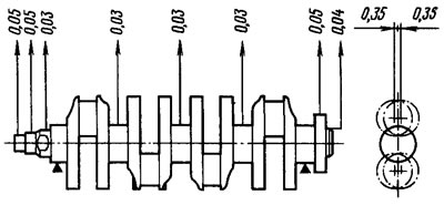
Pic. 44. Checking the crankshaft
Measure the diameters of the main and connecting rod journals. The journals should be ground when worn to a diameter of 0.005 mm less than the minimum diameter for a given crankshaft size, and also if the ovality of the journals is more than 0.03 mm or they have scuffs and risks. The diameters of the necks of normal size are given in tab. 1. Diameters of necks of the repair sizes (reduced by 0.25; 0.5; 0.75; 1.00 mm) equal, respectively, in indigenous: 50.569-0.02; 50,319-0.02; 50,069-0.02; 49,819-0.02 mm; and for connecting rod: 47.60-0.02; 47,35-0.02; 47,10-0.02; 46,85-0.02 mm.
Grind the necks with a decrease to the nearest repair size. The distance between the axes of the connecting rod and main journals should be 35.5+0.025-0.05 mm (piston stroke 71+0.05-0.10 mm), and the radii of the neck fillets are 1.8–2.0 mm.
After grinding, the ovality and taper of the main and connecting rod journals must be no more than 0.005 mm, and the displacement of the axes of the connecting rod journals from the plane passing through the axes of the connecting rod and main journals must be±0.35 mm (see fig. 44). To check, install the shaft with extreme journals on the prisms and set the shaft so that the axis of the connecting rod journal of the 1st cylinder is in a horizontal plane passing through the axis of the main journals. Then the indicator checks the displacement in the vertical direction of the crankpins of the 2nd, 3rd and 4th cylinders relative to the crankpin of the 1st cylinder. After grinding the necks, polish them with diamond paste or GOI paste.
After grinding and subsequent finishing of the necks, the plugs of the oil channels are removed, and then the sockets * of the plugs are driven off with a cutter A.94016/10, put on the spindle A.94016. The crankshaft and its channels are thoroughly washed to remove abrasive residues and blown with compressed air. With mandrel A.86010, new plugs are pressed in and each is minted at three points with a center punch.
* Diameter of sockets for plugs ∅ 10-0.036 mm.
On the first cheek of the crankshaft mark the amount of reduction of the main and connecting rod journals (for example, K 0.25; Ш 0.50).
Inserts
No adjustments can be made on the inserts. In case of scuffing, risks or delamination of the antifriction layer, they are replaced with new ones. If, when checking the liners, it turns out that their further use is possible, then the gap between them and the crankshaft journals is checked.
The gap can be determined by calculation by measuring the diameters of the necks, beds under the liners and the thickness of the liners. If the clearance exceeds the maximum allowable (0.1 mm for connecting rod and 0.15 mm for main journals), replace the liners with others with increased thickness after grinding the necks. A sign of the correct assembly and mating of the necks with the corresponding liners is the free rotation of the crankshaft.
Thrust half rings
As well as on liners, no fitting operations can be performed on half rings. In case of scuffing, risks and delaminations, replace the half rings with new ones. Half rings are also replaced if the axial clearance of the crankshaft exceeds the maximum allowable - 0.35 mm. New half rings are selected with a nominal thickness or increased by 0.127 mm in order to obtain an axial clearance of 0.06-0.26 mm.
The axial clearance of the crankshaft is checked using an indicator, as shown inrice. 31.
Flywheel
Check the condition of the ring gear and replace the flywheel if the teeth are damaged. Surface 1 (pic. 45) flywheel adjacent to the crankshaft flange, and on surface 3 under the clutch disc, scratches and scuffs are not allowed. The non-flatness of surface 3 should be no more than 0.06 mm.
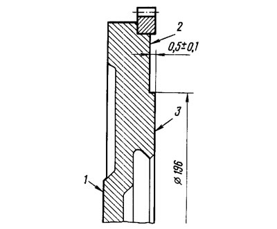
Pic. 45. Checking the flywheel
Scratches and scuffs on surface 3 are removed by a groove, removing a metal layer no more than 1 mm thick. At the same time, surface 2 is also machined, without affecting the gear rim and maintaining the size (0,5±0,1) mm. When turning, it is necessary to ensure the parallelism of surfaces 2 and 3 relative to surface 1. The permissible non-parallelism is not more than 0.1 mm.
The flywheel is installed on the mandrel, centering it along the mounting hole with emphasis on surface 1, and the runout of planes 2 and 3 is checked. In the places indicated by arrows in fig. 45, the indicator should not show beats exceeding 0.1 mm.
When replacing the flywheel, it does not need to be balanced.