
Cylinder block
Compared to the 2108 engine, the height of the cylinder block is reduced by 5.6 mm and is 242–242.2 mm. There are no features in the repair of the cylinder block.
Crankshaft
Due to the reduced piston stroke, the distance between the axes of the connecting rod and main journals has been reduced by 5.2 mm. The crankshafts of 21081 engines can be distinguished by overall dimensions and by the location of the lubrication holes on the crankpins. For crankshafts 21081 they are offset by 3.7 mm from the axis of the neck in the direction of the main journals, and for crankshafts 2108 - by 1.5 mm in the opposite direction from the axis (pic. 185).
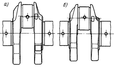
Pic. 185. The location of the lubrication holes on the connecting rod journals of the crankshaft of engines 2108 (A) and 21081 (b)
When grinding the connecting rod journals, the distance between the axes of the connecting rod and main journals must be maintained so that the piston stroke is 60.6+0,05-0,10 mm.
Cylinder head
The cylinder head of engines 21081 and 2108 differ only in the location of the tension roller stud. On engines 2108, the stud is wrapped in the bottom hole 1 (pic. 186), and on engines 21081 - in the upper hole 2.
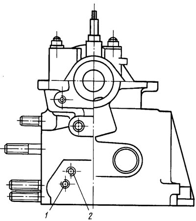
Pic. 186. The location of the tension roller studs on the cylinder heads
Camshaft. It has a different profile and angular arrangement of the cams, since the 21081 engine has different valve timing. To distinguish the camshaft of engines 21081, a cylindrical belt 5 mm wide and 30 mm in diameter is cast on it on the right side from the third cam.
Carburetor
Installed carburetor 21081 - 1107010, differing in calibration data (tab. 33).
The methods of its disassembly, assembly and adjustment are the same as those of the carburetor 2108-1107010.
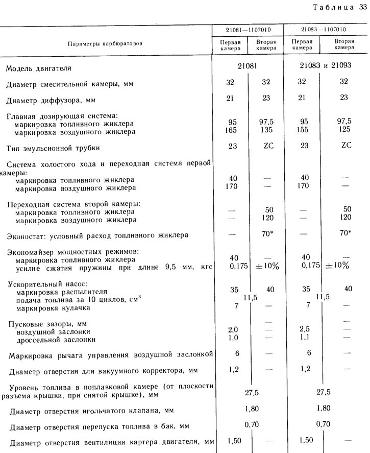
* The conditional consumption of fuel jets is determined by reference jets using a special method. They are not subject to control during operation.
Note. The marking of the jets is determined by the flow rate, which is measured using micrometers. Adjustment of micrometers is carried out according to reference jets.
Exhaust system
An exhaust manifold with one outlet for exhaust gases and a muffler exhaust pipe with one pipeline are installed. The clamp and the bracket for fastening the exhaust pipe to the cylinder block have also been changed.
Ignition system
An ignition distributor type 40.3706-10 is installed with other characteristics of centrifugal and vacuum ignition timing controllers (pic. 187 and 188). To distinguish between these ignition distributor sensors, a red mark is placed on the cover of the vacuum regulator.
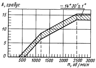
Pic. 187. Characteristics of the centrifugal regulator of the ignition distributor type 40.3706-10:
A - ignition timing;
n - the frequency of rotation of the roller sensor-distributor ignition
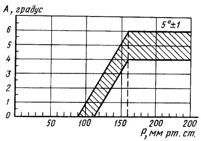
Pic. 188. Characteristics of the vacuum regulator of the sensor-distributor of ignition type 40.3706-10:
A - ignition timing;
R - rarefaction
The initial ignition timing of engines 21081 is 6°±1°.