
Checking the high voltage part
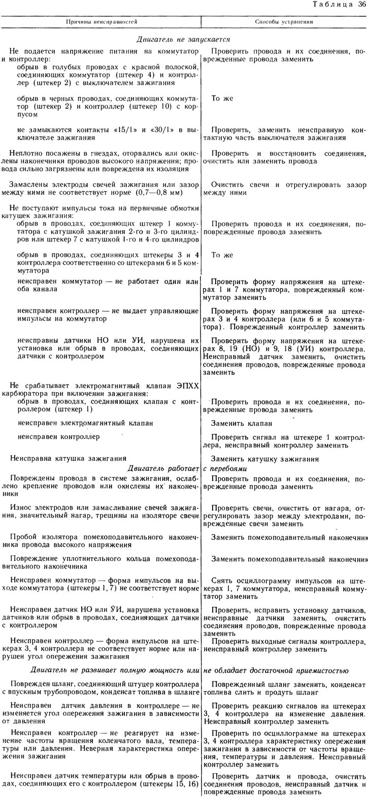
To check, you need a simple spark gap (pic. 193) with two pairs of metal rods 2, 5 (electrodes), fixed on a plate of insulating material (plastic, textolite). The lower part of the rods, together with insulators 7, must correspond in shape and size to the dimensions of the insulator and the tip of the spark plugs. Screws 6 with pointed ends are wrapped in the upper parts of the rods. The gap between the ends of the screws can be adjusted by turning the screws.
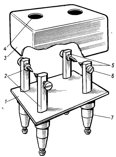
Pic. 193. Discharger for checking the high-voltage part of the system: 1 - insulating base; 2 - electrodes connected to the wires of the spark plugs of the 1st and 4th cylinders; 3 - casing; 4 - viewing window; 5 - electrodes connected to the wires of the spark plugs of the 2nd and 3rd cylinders; 6 - adjusting screws; 7 - insulating sleeves
Care must be taken when checking the high voltage part. For this purpose, the arrester must be covered from above with a cover 3 made of insulating material with viewing windows 4. The arrester must be mounted on the car body.
Disconnect the wire ends from the spark plugs and attach them to the arrester electrodes. Connect the wires from the 1st and 4th candles to one pair of spark gap electrodes, and from the 2nd and 3rd candles to another pair of electrodes. Set the gap between the spark gap electrodes to 7-10 mm and turn the engine over with the starter.
At a low crankshaft speed, there will be noticeable alternate «overshoot» sparks between pairs of electrodes 2 and 5. If sparking on the arrester is normal, then it is necessary to check the spark plugs.
If there is no sparking on one pair of electrodes, then it is necessary to check the electrical circuit from the switch to these electrodes: high-voltage wires, interference suppression tips, ignition coil and connection of the coil to the switch.
When there is no sparking on both pairs of spark gap electrodes, then you should check whether power is supplied to the switch, controller and ignition coils, and also check the switch, controller and NO, UI sensors if the power circuits are OK.
Checking the Switch
Checking the operability of the switch should be carried out using the switch diagnostic tool (development of SLE diagnostics, Riga) or a two-channel electronic oscilloscope by measuring the parameters of input and output pulses (see fig. 191). The simplest test can be performed using the A12.3 W test lamp. To do this, disconnect the low-voltage wires from the ignition coil, attach a lamp to them and crank the engine with a starter. A blinking lamp will indicate that the switch is generating current pulses.
If there are no current pulses on only one ignition coil, then either the wires connecting this coil to the switch are damaged, or one of the switch channels is faulty.
If there are no current pulses on both coils, then either the supply voltage is not supplied to the ignition coils, switch or controller (blue wire with red stripe), or the malfunction must be looked for further. Perhaps it is in the switch, the controller, or in the connections between them.
If you have a known-good switch, you can replace the car's switch with it and check the operation of the ignition system. Its normal operation in this case will indicate that the car had a faulty switch.
Controller check
The performance of the controller and the accuracy of reproducing the characteristics of the ignition timing is checked using «Tester MSUAD» (SLE diagnostics, Riga) in accordance with the instruction manual for the tester. You can check the operation of the controller using a two-channel electronic oscilloscope using the following method.
1. Connect an electronic oscilloscope to the diagnostic outputs of the controller in the following order:
- apply angular pulses to the input of the amplifier of the first channel (plug 7 controller);
- apply reference pulses to the input of the amplifier of the second channel (plug 5 controller);
- apply a diagnostic pulse C3 to the input of the external trigger of the oscilloscope sweep (plug 13 controller);
2. Enable «waiting» time mode. oscilloscope turntable, synchronization - transition from a high signal level to a low one (moment of sparking);
3. Calculate the ignition timing using the formula
Θ = nUI·1.4°,
where nUI - the number of transitions of the ID signal from a high level to a low level and vice versa in the sweep range of the oscilloscope from the moment of sparking to the front (transition from low to high) NO signal (V. m. t.); 1.4°- angle of rotation of the crankshaft for half the period of angular impulses.
Example. Assume that during the crankshaft rotation at an angle of 0, eight transitions of the UI signal are observed (see fig. 191, a), then: Θ = 8 1.4 = 11.2°.
The simplest check of the controller's performance can be performed using the indicator, made according to the scheme in Fig. 194. The indicator uses MLT type resistors (1 W), a transistor of the KT817B type, and an A12 car lamp was taken as an indicator lamp (3 W).
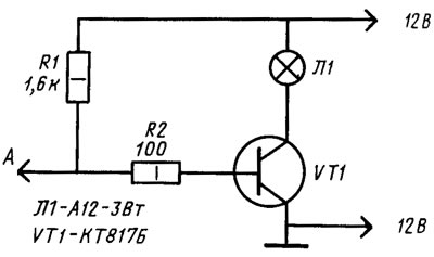
Pic. 194. Indicator circuit for checking the controller
To test the controller, connect the leads «—» and «+» indicator with battery, disconnect the plug connector from the switch and connect the input A of the indicator to the plug «5» this block (connected with white wire). Turn the engine over with a starter. If the indicator lamp flashes, the controller generates pulses «Channel selection».
Similarly, the presence of SZ pulses is checked by connecting the indicator input to the plug «6» (blue wire goes to it) wiring harness disconnected from the switch.
If there are no pulses, then they check whether the supply voltage is supplied to the controller and whether there is a break in the wires connecting the controller to the switch and to the NO and UI sensors. If the wires are intact and the supply voltage is supplied to the controller, but there are no pulses, then it is necessary to check the controller on the stand.
To check the control function of the EPHX solenoid valve of the carburetor, disconnect the green wire from the limit switch 8 (see fig. 190) carburetor and connect the tip of this wire to the body. Then the engine is started and the crankshaft speed is gradually increased. At 1750 rpm (measured by some additional tachometer) valve should turn off. Now slowly reduce the speed. When it drops to 1650 rpm, the valve should turn on.
Set the speed to 2000 rpm, disconnect the tip of the wire going to the carburetor limit switch from the body, and then reconnect it to the body. When the wire is disconnected from the body, the valve should turn on, and when connected to the body, it should turn off.
The actuation moment of the valve can be determined by a characteristic click or by using a voltmeter connected to the valve and body. If the valve is on, then the voltmeter should show a voltage of at least 10 V, and if it is off, then no more than 1.5 V.
Checking the ignition coil
At the ignition coil, the resistance of the windings is checked, whether there is a short circuit between the windings and a breakdown of the insulation to the housing. Primary resistance (0,5±0,05) Ohm, and the secondary - (11±1,5) kOhm
Breakdown of insulation on the body is detected by burnout or melting of the plastic shell of the coil on the surface adjacent to the mounting bracket.
Checking the sensors of reference and angular impulses. The sensor installation should be checked. For normal operation of the sensor, it is necessary that the gap between the sensor and the top of the flywheel ring tooth (or the end face of the pin for the NO sensor) was in the range of 0.3-1.2 mm (pic. 195). The gap can be determined by removing the sensor, measuring the distance from the surface of the clutch housing to the top of the tooth and subtracting 25 mm from this.
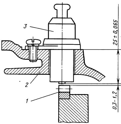
Pic. 195. Installation of the sensor of angular impulses: 1 - flywheel crown; 2 - clutch housing; 3 - sensor
The resistance of the sensor winding is (400±50). Ohm is measured with an ohmmeter. The shape and amplitude of the pulses generated by the sensor is checked by an electronic oscilloscope (see fig. 192).
You can roughly assess the presence of pulses generated by the sensor using an AC voltmeter, turning the engine with a starter.
Sensor winding resistance and voltage can be measured with a combined instrument (e.g. C4317).
Checking the Temperature Sensor
The sensor is checked by inserting it into a tank of water or coolant, which can be heated. Connect a 12 V power supply and a voltmeter to the sensor (pic. 196). The voltmeter must be DC with a measurement limit of 0-5 V and an accuracy class of 1.5 (e.g. C4317). The temperature sensor supply current is set by resistor R1.
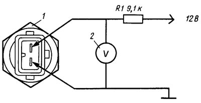
Pic. 196. Scheme for checking the temperature sensor: 1 - sensor; 2 - voltmeter
Turning on the water heating, measure the voltage drop across the sensor at different temperatures in the tank. The voltage drop should not differ by more than±0.1 V from the calculated one, determined by the formula given in sec. «Device Features».
Testing at the stand
For an accurate functional check of the elements of the microprocessor-based engine control system, it is necessary to use a special stand consisting of a 21083 engine flywheel simulator and elements of the LMCM system connected using a wiring harness in accordance with rice. 190.
The flywheel simulator is an aluminum disk with a pressed-on ring gear of the engine flywheel 21083 and with a marker pin for the NO sensor fixed on the disk. The disc is mounted on the motor shaft and covered with a metal casing with holes for NO and UI sensors. To check the parameters of the sensors, the seats under them are made in such a way that with the help of gaskets it is possible to adjust the installation gap within 0.3-1.2 mm.
Instead of spark plugs, the stand is equipped with arresters similar to those shown on rice. 193.
The stand is completed with the following instruments and equipment:
- DC voltage source 0-15 V, 0-10 A (for example, TES-15);
- two-channel electronic oscilloscope (e.g. C1-6I);
- combined measuring instrument (e.g. C4317);
- tester MSUAD with a vacuum unit (SLE diagnostics, Riga);
- switch tester (SLE diagnostics, Riga).
In the work on diagnosing a microprocessor-based engine control system, it is necessary to be guided by the following materials:
- specifications for type controllers «Electronics MS-2713-01» BK0.305.077 TU;
- specifications for a two-channel switch type 42.3734 - TU 37.464.008-85;
- technical description and operating instructions for the MSUAD tester;
- technical description and operating instructions for the switch tester.