
Setting the fuel level in the float chamber
The fuel level necessary for the normal operation of the carburetor is ensured by the correct installation of serviceable elements of the locking device.
Correct installation of float 1 (pic. 54) checked by gauge 4, for which it is installed perpendicular to cover 2 with gasket 3. The cover must be held horizontally with the floats up. There must be a gap of no more than 1 mm between the gauge along the contour and the floats. If necessary, adjust by bending the tongue and float levers. The bearing surface of the tongue must be perpendicular to the axis of the needle valve and must not have dents or nicks.
Pic. 54. Setting the fuel level in the carburetor float chamber
Trigger Adjustment
When turning lever 4 (see fig. 17) control of the air damper 5 to failure counterclockwise, the air damper must be completely closed under the action of the spring 7. If the damper is not closed, eliminate the cause of jamming.
With the air damper completely closed, manually press the rod 3 of the starting device until it stops. In this case, the air damper should open to (3±0,2) mm (starting clearance B). If necessary, adjust the gap with screw 2.
Throttle valve 10 of the first chamber with a fully closed air damper should be ajar by 0.88 mm (starting gap D). Adjust this gap with screw 9.
Carburetor Drive Adjustment
With pedal fully depressed 1 (pic. 55) throttle control, the throttle valve of the first chamber must be fully open and sector 15 must not have an additional stroke. When the pedal is released, the throttle should be fully closed. If this is not the case, adjust the position of the pedal and throttle valve with adjusting nuts 13 on the front tip of the drive cable.
In the air damper drive, the shell 10 of the rod 14 is fixed so that it protrudes by 40 mm. The rod 14 is attached to the air damper control lever 16 so that when the handle 8 is pulled out, the air damper is completely closed, and when the handle is recessed, it is completely open.
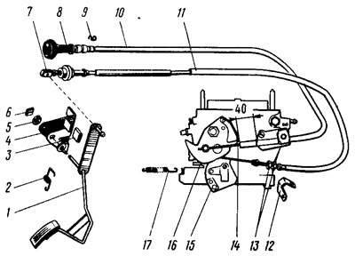
Pic. 55. Carburetor control drive: 1 - throttle control pedal (accelerator); 2, 17 - return springs; 3 - pedal stop gasket; 4 - bracket; 5 - bushing; 6 - locking bracket; 7 - cable tip; 8 - air damper control handle; 9 - retaining spring; 10 - thrust shell; 11 - cable sheath; 12 - adjusting tip bracket; 13 - adjusting nuts; 14 - air damper drive rods; 15 - throttle control sector; 16 - air damper control lever
Engine idle adjustment
Idle adjustment elements include adjusting screw 2 (pic. 56) quality (composition) mixture and adjusting screw 1 of the mixture amount. Adjusting screw 2 with O-ring 3 is closed with plug 4. To gain access to the screw, it is necessary to break the plug.
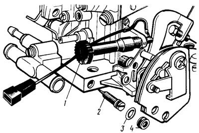
Pic. 56. Screws for adjusting the carburetor idle system
Idle speed adjustment must be carried out on a warm engine (coolant temperature should be 90-95°C) with adjusted gaps in the gas distribution mechanism, with a correctly set ignition timing and with a fully open air damper.
Adjusting screw 1 of the amount of the mixture is set according to the tachometer of the stand, the engine crankshaft speed is in the range of 750-800 rpm. Then adjusting screw 2 quality (composition) mixtures achieve a concentration of carbon monoxide (SO) in exhaust gases within 0.5-1.2% at a given screw position 1 (CO concentration is adjusted to 20°C and 760 mm Hg. Art.). Screw / restore the crankshaft speed to 750-800 rpm. If necessary, adjusting screw 2 restores the CO concentration to 0.5-1.2%.
At the end of the adjustment, sharply press the accelerator and release it; At the same time, the engine should increase the crankshaft speed without interruption, and when it decreases, it should not stall. If the engine is stopped with screw 1, the crankshaft speed is increased within 750-800 rpm.
After adjustment, a new plastic plug 4 is installed in the hole for the adjusting screw 2.