
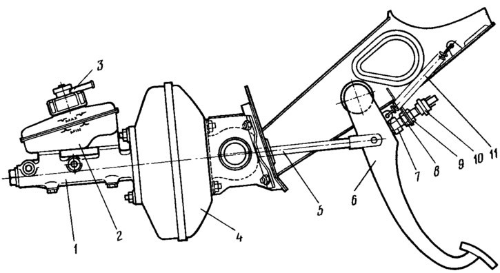
Pic. 89. Brake pedal assembly with vacuum booster and master cylinder:
1 - main cylinder; 2 - tank; 3 - emergency liquid level sensor; 4 - vacuum amplifier; 5 - pusher; 6 - brake pedal; 7 - brake light switch buffer; 8, 9 - brake light fastening nuts; 10 - stoplight switch; 11 - pedal return spring.
If the brake light switch is too close to the pedal, it will not return to its original position, valve 18 (see fig. 78), pressing against the body 21, will disconnect the cavities A and B, and there will be an incomplete disengagement of the wheels when the pedal is released.
If by moving the brake light switch it is not possible to eliminate the incomplete release of the brake mechanisms, then you should contact the service station, where they will adjust the protrusion of the adjusting bolt 4 (see fig. 78) vacuum booster relative to the mounting plane of the master cylinder flange (size 1.25—0,2 mm).