
Between building 9 (pic. 78) and cover 11 is clamped rubber diaphragm 10, the inner belt of the hole which goes into the annular groove of the body 21 of the valve. The diaphragm, together with the valve body, divides the cavity of the vacuum booster into two chambers: vacuum A and atmospheric B. Chamber A is connected to the engine intake pipe through a tip and a hose. A vacuum valve is located in the hose tip to prevent the combustible mixture from entering the vacuum cavity A. To seal the connection between the hose tip and the amplifier housing, a rubber flange is installed between them.
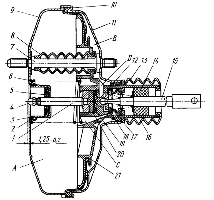
Pic. 78. Vacuum booster:
1 - stock; 2 - sealing ring of the flange of the main cylinder; 3 - a cup of the amplifier case; 4 - adjusting bolt; 5 - rod seal; 6 - diaphragm return spring; 7 - amplifier pin; 8 - sealing case; 9 - amplifier case; 10 - diaphragm; 11 - amplifier housing cover; 12 - piston; 13 - protective cover of the valve body; 14 air filter; 15 - pusher; 16 - pusher return spring; 17 - valve spring; 18 - valve; 19 - valve body bushing; 20 - stock buffer; 21 - valve body; A - vacuum chamber; B - atmospheric chamber; D, C - channels.
In the cover of the amplifier, two studs 7 are rolled, which perform several functions: they serve to fasten the vacuum booster and the main cylinder, they are guides for the valve body 21 and provide the necessary rigidity and strength of the connection of the body 9 of the amplifier with the cover 11. The latter made it possible to reduce the weight of the amplifier by reducing wall thickness of the body and cover. At the outlet of the housing and cover, the studs are sealed: on the side of the body with rubber sealing washers put on the studs, on the other hand, by flaring the studs on the cover. Sealing covers 8 are put on the studs. On the one hand, they are tightly planted on the studs, on the other, they are connected to the movable valve body. The tightness of their connections is ensured by annular grooves of a certain profile, which cover the edges of the openings of the valve body. Due to this, chambers A and B are isolated from each other.
The valve body 21 is plastic. Under the action of the return spring 6, it, together with the diaphragm, is pressed towards the amplifier cover. The shank of the valve body at the exit from the cover is sealed and at the same time protected by a corrugated protective cover 13. The sealing part of the cover has a complex configuration, which forms several working edges adjacent to the shank. The front part of the cover is held in the cover of the amplifier by the edges of the cover, bent into the groove of the cover. The protective part of the boot covers the shank of the valve body and is held inside the shank by a ring.
In the valve body there is a rod 1 of the main cylinder drive with a support sleeve, a piston 12, a valve body sleeve 19, a stem buffer 20, a valve 18, two springs 16 and 17, an air filter 14 and a pusher 15. The support sleeve is pressed onto the rod. It rests through the rubber buffer 20 and the plastic sleeve 19 into the valve body. An adjusting bolt 4 with a spherical head is screwed into the end hole of the rod. This bolt adjusts the output of the rod from the amplifier housing (1,25—0,2 mm). At the outlet of the housing, the rod is covered by a seal 5. To seal the gap between the flange of the main cylinder and the housing of the vacuum booster, a rubber ring 2 is installed in the housing seat.
The piston 12 is rigidly connected to the valve body due to the rolling of the disc at the end of the piston. The ball head of the pusher is crimped into the piston seat. Thus, the valve body, piston and pusher form a single non-separable unit. A rubber valve 18 is pressed against the end of the piston by a spring 17. For rigidity, a steel washer is mounted in the valve head. A support sleeve is pressed against the rear end of the valve by a spring 16. The other end of the spring rests against the washer of the air filter 14, made of polyurethane foam.
In the initial position of the brake pedal, the pusher 15, together with the valve body 21 and the stem 1, are pressed by the spring 6 to the rearmost position. In this case, the valve head moves away from the valve body and through the resulting gap and channels C and K of chambers A and B communicate with each other. Therefore, when the engine is running, the vacuum from the engine intake pipe through the vacuum valve is transmitted to chamber A and through channels C w K and gaps to chamber B.
When you press the brake pedal, the pushrod moves along with the piston and valve body. Following the piston, the valve moves under the action of the spring 17 until it stops against the seat of the valve body. When adhering to the seat, the valve separates chambers A and B. With further movement of the piston, its end moves away from valve 18, and through the resulting gap, chamber B communicates with the atmosphere. In this case, air enters chamber B through filter 14, then through the gap formed between the piston and valve and then through drip K, creating pressure on diaphragm 10. Due to the pressure difference in chambers A and B and the force on the brake pedal, the valve body moves together with rod 1, which in turn acts on the piston of the brake master cylinder.
If the driver stops further pressing the brake pedal without removing his foot from the pedal and leaving it depressed in some middle position, then the valve body moves forward under the action of atmospheric pressure until the gap between the piston and the valve is selected, since the piston remains stationary. Therefore, air stops entering chamber B and further movement of the valve body will stop. At this moment, a gap is formed between the valve body seat and the valve and the excess pressure from chamber B is transferred to chamber A, that is, the pressure in both chambers will equalize and the servo action of the amplifier will stop.
When the brake pedal is released, it returns to its original position under the action of a return spring and pulls the pusher 15, the piston 12 and the valve body 21. Spring 6 also acts in the same direction. The rear end of the piston is pressed against the valve head, which stops the supply of atmospheric air, and then removes the valve from the body seat. In this case, chambers A and B communicate with each other and, under the action of spring 6, the valve body with the stem will return to its original position.