
The brake mechanism consists of a guide 2 (pic. 83) pads, caliper 3, two brake pads 4 and brake disc 1. The drive of the pads is carried out from the wheel cylinder 5.
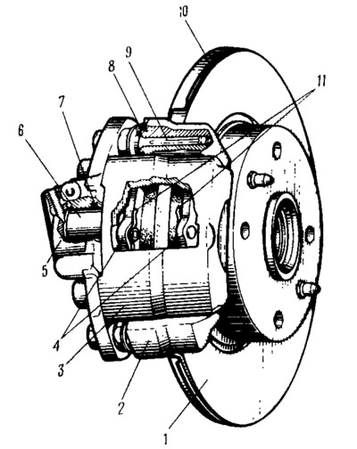
Pic. 83. Front wheel brake:
1 - brake disc; 2 - guide pads; 3 - support; 4 - brake pads; 5 - cylinder; 6 - piston; 7 - sealing ring; 8 - sewn cover of the guide pin; 9 - guide pin; 10 - wired casing; 11 - pad spring.
Guide 8 (pic. 84) block is made of high-strength cast iron in the form of a bracket, has four bosses. In two of them, threaded holes are made for fastening the guide pads to the steering knuckle, in the other two, holes for pins are drilled 9 (see fig. 83) caliper. The pad guide has a longitudinal groove through which the brake disc passes, and two openings for placing the brake pads. The configuration of the openings is made in the form of brake pads. In addition, there are two shelves in the side openings, to which brake shoes 4 are pressed by springs 11. All this ensures a tight fit of the brake shoes in the guide and prevents their vibration.
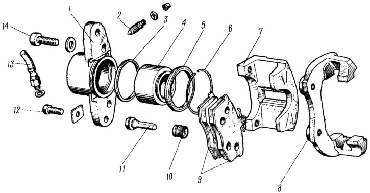
Pic. 84. Front wheel brake (detailing):
1 - wheel cylinder; 2 - fitting for pumping the brake drive; 3 - sealing ring; 4 - piston; 5 - protective cap; 6 - retaining ring; 7 - support; 8 - guide pads; 9 - brake pads; 10 - protective cover; 11 - guide pin; 12 - bolt for fastening the guide pin; 13 - brake hose; 14 - a bolt of fastening of the cylinder to a support.
Caliper 7 (see fig. 84) cast from ductile iron. At the bottom it has a groove for the brake pads, and in the center of the casting there is a through viewing window into which the lugs of the brake pads are pressed. Through this window, the wear of the brake pads is visually determined. The springs of the pads rest against the steps of the window. This ensures that the brake pads are pressed against the guide and fixed relative to the caliper. Cylinder 1 is fastened with its flange with two bolts 14 to caliper 7, forming «floating» bracket. To ensure the joint mobility of the caliper and the wheel cylinder relative to the guide, they are connected to the guide pads not rigidly, but with the help of fingers 9 (see fig. 83), which are installed in the holes of the guide. Guide pins are bolted 12 (see fig. 84) to the flange of the wheel cylinder. Bolts of fastening are fixed by locking plates. The pins are lubricated during assembly to prevent corrosion of this joint to ensure consistent force to move the caliper, regardless of the age of the vehicle. So that when moving the fingers in the holes, air resistance is not created due to its compression, there are three flats on the finger shaft. A protective cover is put on the annular grooves of the finger and the guide 8 (see fig. 83), which protects the fingertips from water and dirt.
Brake pads - steel, have a shape that ensures their snug fit to the guide pads. At the top of the pads are lugs, which, as indicated above, enter the caliper window.
Spring 11 is attached to the shoe with a finger. When installing the caliper, it presses on the spring, ensuring that the shoes are pressed against the guide. A friction lining is glued to the block.
The wheel cylinder is attached to the caliper and shoe guide as described above. A hollow piston 6 is installed in the cavity of the cylinder 5 (see fig. 83) with a diameter of 48 mm, which is sealed in the cylinder with a rubber ring 7. This ring has a trapezoidal shape. It is located in the groove of the cylinder and tightly covers the piston. As the piston moves, it drags the ring along with it, twisting it in the cylinder groove. Due to the elasticity of the sealing ring, the piston then returns to its original position. The cylinder cavity is protected by a rubber cap 5 (see fig. 84), the edges of which are laid in the grooves of the piston and cylinder. The cylinder has two holes. A fitting 2 is screwed into one of them for pumping the brake mechanism drive, into the other, a hose fitting 13 for supplying fluid to the cylinder.
Brake disc 1 (see fig. 83) cast from gray cast iron. Six holes are drilled in the disc hub, four of them are for the wheel disc mounting bolts, two are for the wheel disc guide pins. The working surface of the disc is made with great precision. The normal thickness of the disc is 12 mm, the maximum allowable is 10.8 mm. The brake disc is closed from the inside with a protective cover 10, which is attached to the steering knuckle.