
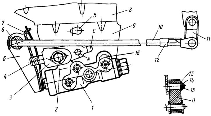
Pic. 81. Drive pressure regulator:
1 - pressure regulator; 2, 16 - regulator mounting bolts; 3 - arm of the pressure regulator drive lever; 4 - pin; 5 - regulator drive lever; 6 - axis of the lever; 7 - lever spring; 8 - body bracket; 9 - pressure regulator mounting bracket; 10 - elastic lever drive regulator; 11 - earring; 12 - earring staples; 13 - washer; 14 - retaining ring; 15 - bracket pin; A, B, C - holes.
The pressure regulator is attached with two bolts to the bracket shelf 9, which in turn is attached to the bracket 8 of the body floor. In this case, the front, longer bolt 2 simultaneously fastens the fork bracket 3 of the pressure regulator drive lever. To prevent the bracket 3 from turning relative to the bolt 2, its protrusion enters the groove C of the bracket 9. Thanks to this groove and oval holes in the bracket 3 for the fastening bolt 2, the bracket 3, together with the lever 5 of the pressure regulator drive, can be moved relative to the pressure regulator body when adjusting its drive.
A finger is welded to the forked bracket 3, which is a support for the lever 5. A pin 4 is pressed into the hole of the finger, relative to which the two-arm lever 5 can be rotated, having a box-shaped section. In the upper holes of its two shelves there is an axis 6, through the hole of which the end of the elastic lever 10 of the pressure regulator drive passes. The axis of the lever and the elastic lever are locked by a common lock. To prevent the transmission of vibrations and vibrations from the drive parts to the pressure regulator piston, a leaf spring 7 is installed on the lever support 5. Its upper end enters the slot of the bent end part of the lever 5, and the lower end is adjacent to the lower arm of the lever. The elastic lever 10 freely passes through the oval hole of the spring 7. The other end of the lever 10 is pivotally connected to the earring 11, which swings on the pin 15 of the rear suspension arm bracket. The earring is held on the finger by a lock washer 13, and connected to the end of the elastic lever by a bracket 12.
When the rear suspension moves, the force with which lever 10 acts through lever 5 on the regulator piston changes. The more the rear suspension is loaded, the more force will be transferred to the regulator piston. This is due to the fact that the regulator is fixedly mounted on the body, and the drive is received from the swinging suspension arm.
In building 1 (pic. 82) of the pressure regulator, a plug 16 with a sealing gasket 15 is screwed in at one end, and a sleeve 5 is installed at the other end, fixed in the housing with a retaining ring 4. The piston 2 is located in the sleeve 5. At the outlet of the housing, it is sealed with a protective cover 3. The piston head enters with a gap into the sleeve 7. The spring 6 presses through the washers 22 the sealing ring 23 to the end face of the sleeve 5, and the seal 21 to the sleeve 7.
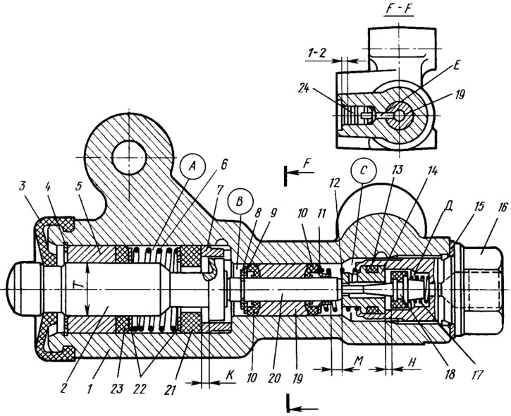
Pic. 82. Pressure regulator:
1 - regulator housing; 2 piston; 3 - protective cap; 4, 8 - retaining rings; 5 - piston sleeve; 6 - piston spring; 7 - housing sleeve; 9, 22 - thrust washers; 10 - pusher sealing ring; 11 - support plate; 12 - pusher bushing spring; 13 - sealing ring of the valve seat; 14 - valve seat; 15 - sealing gasket; 16 - cork; 17 - valve spring; 18 - valve; 19 - pusher bushing; 20 - pusher; 21 - piston head seal; 23 - piston rod seal; 24 - plug; A, D - chambers connected to the main cylinder; B, C - chambers connected to the wheel cylinders of the rear brakes; K, M, H - gaps.
A rubber-metal valve 18 is installed in the plug 16, pressed against the seat 14 by a spring 17. The tightness of the seat 14 in the plug is ensured by the sealing ring 13. The seat is rolled in the plug 16. it with two rubber rings 10. The spring 12 through the plate 11 presses the sleeve 19 with sealing rings 10 to the washer 9, which is held on the pusher 20 by the retaining ring 8. The sleeve 19 has a radial hole, which coincides with the hole E of the pressure regulator body. Outside, this hole is closed with a rubber plug 24. It should be deepened in the hole in the pressure regulator housing by 1... 2 mm. If liquid leaks from under the plug or the plug is squeezed out of the hole, then the rings 10 do not provide a tight connection.
Chambers A and D of the pressure regulator are connected to the main brake cylinder, and chambers B and C are connected to the brake cylinders of the rear wheels.
When the brake pedal is in its original position, piston 2 is pressed by lever 5 (see fig. 81) through the leaf spring 7 to the pusher 20 (see fig. 82), and he, in turn, rests on the valve seat 14. In this case, the pusher presses the valve 18 from the seat and a gap 11 is formed between them, equal to 1.3... 1.7 mm, and between the seal 21 and the piston head - a gap K equal to 1.6... 2.4 mm. Through the formed gaps, chambers A and D freely communicate with chambers B and C, respectively. When the brake pedal is pressed, the fluid from the master cylinder flows through chamber A, gap K and chamber B to the right rear, and through chamber D, gap H and chamber C to left rear wheel cylinder. With an increase in the effort on the brake pedal, and hence the fluid pressure, the force on piston 2 will also increase, tending to push it out of the regulator housing. When the force on the lever 5 from the fluid pressure exceeds the counteracting moment from the elastic lever, the piston begins to move out of the housing. Following the piston, under the action of springs 17 and 12, the pusher 20 is displaced together with the sleeve 19 and rings 10. In this case, the gap M between the plate 11 and the seat 14 increases, and the gaps I and K decrease. When the gap H is completely selected and the valve 18 isolates the chamber D from the chamber C, the pusher 20, together with the parts located on it, stops moving after the piston. From this point on, the pressure in chamber C will change depending on the pressure in chamber B. With a further increase in the effort on the brake pedal, the pressure in chambers D, A and B will increase and the piston will continue to move out of the body. At the same time, under the pressure of the liquid, the sleeve 19, together with the sealing rings 10 and the plate 11, will move towards the plug 16. In this case, the gap M and the volume of the chamber C will decrease. With a decrease in volume C, the pressure in it, and hence in the rear wheel brake drive, will increase and will almost always be equal to the pressure in chamber B.
When gap K is completely selected, i.e., piston head 2 touches seal 21, the pressure in chamber B, and hence in chamber C, will increase to a lesser extent compared to chamber A due to throttling of the fluid when it flows between the piston head and seal 21. The dependence of the pressure in chambers B and C on the pressure in chamber A is determined by the ratio of the difference between the areas of the head and the cross section of the piston at diameter T to the area of the head.
With an increase in the load of the car, the elastic lever 10 (see fig. 81) will be loaded more from the rear suspension arm and the force on the piston from the arm 5 will increase. This means that the moment of contact between the piston head and the seal will be achieved at a higher pressure in the master brake cylinder. Thus, the relative effectiveness of the rear brakes with increasing load on the car increases with the same effort on the brake pedal as with less load.
In case of circuit failure «right front - left rear brakes» the pressure in chamber C will drop, and the sealing rings 10 and the sleeve 19 under the pressure of the fluid in chamber B will shift towards the plug 16 until the plate 11 stops in the seat 14. The pressure in the brake of the rear right wheel will be determined by the part of the regulator, which includes the piston 2 c seal 21 and bushing 7. The operation of this part of the regulator in the event of a failure of the named circuit is similar to operation in a working system. The nature of the change in pressure at the outlet of the regulator is the same as with a working system.
In case of circuit failure «left front - right rear brakes» (when pressure drops in chamber B) brake fluid pressure pusher 20 with sleeve 19 and sealing rings 10 are displaced towards the piston, pushing it out of the housing. The gap M increases and the gap H decreases. When the valve 18 touches the seat 14, the pressure increase in the chamber C stops, i.e. the regulator in this case works as a pressure limiter. However, the achieved pressure is sufficient for reliable operation of the rear left wheel brake. It is equal to 17... 21 kgf / cm2. The response time of the valve 18, i.e., its pressing against the seat 14, depends on the speed of braking and the rate of pressure drop of the liquid in the damaged circuit.