
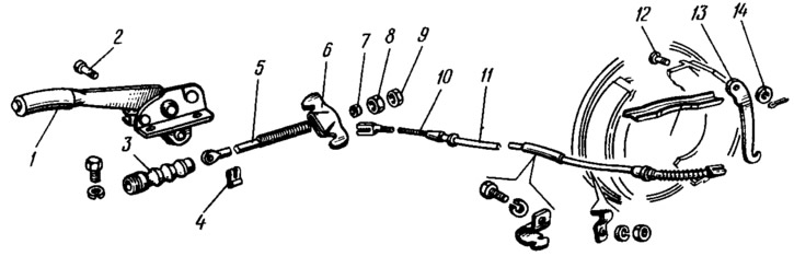
Pic. 87. Parking brake (detailing):
1 - parking brake lever assembly with bracket; 2 - thrust finger; 3 - protective cover; 4 - locking bracket; 5 - thrust; 6 - cable equalizer; 7 - washer; 8 - adjusting nut; 9 - locknut: 10 - cable; 11 - cable sheath; 12 - axis of the lever; 13 - lever for manual drive of the pads; 14 - washer.
Lever 10 (see fig. 85) the manual drive of the pads is pivotally connected with a pin 9 to the rear pad of the brake mechanism. This lever on the finger is fixed through the thrust washer with a cotter pin. The ribs of the rear shoe and lever 10 abut against the groove of the expander bar 8. The edge of the front shoe 4 enters the groove of the other end of the bar. The tip of the cable 10 is put on the lower end of the lever 10 (see fig. 87). The other tip of this cable is connected to the equalizer 6, which is attached to the rod 5 with an adjusting nut 8 with a washer 7. The position of the adjusting nut is fixed with a lock nut 9. The front end of the rod 5 is connected with a finger to the lever 1 of the parking brake drive. The connecting pin is locked with a bracket 4. The front part of the rod is protected from water and dirt by a rubber boot 3.
Lever 1 is mounted on a bracket together with a toothed sector. This node is non-detachable. It is attached to the floor of the body. In engagement with the gear sector there is a latch, which is turned off through the rod with the lever button. All parts are assembled in the inner cavity of the lever 1. To turn off the parking brake warning lamp on the lever 1 there is a stop acting on the switch rod.
The cable 10 is located in a multilayer sheath 11, which has lugs at the ends. The rear tip is attached to the brake shield, and the front one fits into the socket of the underbody bracket. In addition, the cable additionally rests on two rear suspension arm brackets and a body bracket. Multi-point supports of the cable sheath provide free, without jamming, movement of the cable in its sheath, and also protect the cable from damage. To return the cables to their original position when releasing, springs are installed at the rear ends of the cables.
When moving the lever 1 of the parking brake up, the cables are stretched and rotated on the fingers 9 (see fig. 85) levers 10 for manual control of the pads. Spacers 8 press the front pads against the drums. Further rotation of the levers on the fingers stops. Then they begin to turn around the points of contact with the spacer bars and press the rear pads against the drums with short arms. When the parking brake is applied, the latch freely jumps over the teeth of the sector until the pads are completely pressed against the drums, and in this position the lever is fixed, catching on the tooth of the sector. To release the brake, press the lever button 1 to raise the latch and lower the lever.