




Windscreen wipers can be of domestic production or manufactured in Hungary. They are interchangeable in terms of connection and mounting dimensions. The gear motors of these wipers are also interchangeable, although they have some differences in design.
The wiper motor is a permanent magnet-excited, three-brush motor with two rotation speeds. The first frequency (low) is provided by supplying voltage to the brush located in the geometric neutral of the electric motor, and the second frequency (high) is provided by supplying voltage to the brush shifted from the geometric neutral.
To protect the electric motor from overloads when the brushes freeze to the glass or there is high resistance to their movement, a thermal bimetallic fuse is installed in the wiper. In VNR-made gear motors, the fuse is installed under the gear motor cover on the limit switch panel, and in domestic gear motors, it is located on the gear motor mounting bracket.
Right steering column switch lever 7 (figure 128) one of three operating modes of the cleaner can be switched on. One mode with intermittent movement of the brushes and two constant modes, but with different speeds of movement of the brushes.
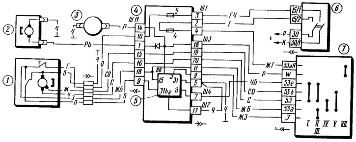
Figure 128. Windshield wiper and washer circuit diagram:
1 - wiper motor; 2 - washer motor; 3 - electromagnetic valve for turning on the windshield washer; 4 - mounting block; 5 - windshield wiper relay; 6 - ignition switch; 7 - windshield wiper and washer switch.
When the ignition is switched on, voltage is supplied to contact "53a" of steering column switch 7 along the following path: from closed contacts "30/1" and "15/1" of ignition switch 6, through fuse "5" of mounting block 4 to bimetallic fuse of electric motor 1. Then, via yellow wires with a white stripe and through the mounting block, it goes to terminal "15" of relay 5 and to contact "53a" of switch 7. Depending on which contacts of the switch contact "53a" closes, one or another windshield wiper mode is activated.
[The information is posted on the portal: www.VazBook.ru]
Low speed of movement of the brushes is ensured in position "71/" of lever 19 (see figure 4) of the steering column switch. Contacts "53a" and "53" are closed. Current flows from contact "53" along the gray wire, through the mounting block to the brush of electric motor 1, which is in geometric neutral. Then the current flows through the anchor of the electric motor to the "ground".
High speed of brush movement is achieved in the "V" position of the steering column switch lever. The "53a" and "53v" contacts of the switch are closed and the current flows along the gray wire with an orange stripe, through the mounting block it goes to the electric motor brush, shifted from the geometric neutral.
The intermittent operation of the wiper is provided by the electronic relay 5 installed in the mounting block. In positions "II" and "III" of the steering column switch 7, contacts "53a" and "I", as well as "53" and "53e" are closed. From the contact "I" of the switch, voltage is supplied to the terminal "I" of the relay. It is triggered and closes its terminals "15" and "S". Current flows from the terminal "S" to the closed contacts "53e" and "53" of the switch 7, and then through the gray wires to the brush of the electric motor 1, which is in geometric neutral. The wiper begins to operate at low speed. The electronic circuit of the relay disconnects and again supplies voltage to the terminal "S" with a frequency of 14 cycles per minute, creating intermittent operation of the wiper.
Windscreen wiper relay 5 consists of an electronic circuit and an electromagnetic relay. In the initial position, the relay armature contact (terminal "S") is closed with terminal "31v", i.e. terminals "S" and "31v" are normally closed. When control voltage is supplied to terminals "86" or "I", the relay electronic circuit switches on the power supply of the electromagnetic relay winding, it operates and closes terminals "5" and "15". The supply voltage is supplied to terminal "15". Terminals "31" and "R" are connected to "ground".
Relay 5, in addition to ensuring intermittent operation of the wiper, has another function. It switches on the low speed of the wiper (if it is turned off or was running in intermittent mode) when supplying washer fluid to the windshield. After the fluid supply is turned off, the relay does not turn off the wiper immediately, but after 2...4 full cleaning cycles at low speed.
To switch off the wiper, the switch lever 7 is moved to the initial position, in which contacts "53" and "53e" are closed. At the same time, the terminals "S" and "31v" of the relay are closed. The current supplying the armature winding of the electric motor goes through the closed contacts of the limit switch in the electric motor, through the closed terminals "31v" and "S" of the relay, then through the closed contacts "53e" and "53" of switch 7 and to the electric motor brush, which is in geometric neutral. The wiper operates at low speed. At the moment when the wiper brushes return to the initial position, the cam protrusion of the worm gear of the reducer opens the contacts of the limit switch and the power supply to the armature winding of the electric motor is disconnected. The armature of the electric motor will stop and the wiper brushes will remain in the lower position.
The electric motor 2 of the washer is combined into one unit with the pump. From the pump, the liquid is pumped into three lines: to the windshield, to the headlights and the rear window. Each of the lines has an electromagnetic valve that shuts off the supply of washer liquid. Thus, in the line supplying liquid to the windshield there is valve 3, in the line supplying liquid to the headlights there is valve 2 (see figure 129), and the supply of liquid to the rear window is blocked by valve 4. When the supply of washer liquid to any of the windows is turned on, the pump electric motor is turned on and voltage is supplied to the corresponding valve. It is triggered, opens the corresponding line and the liquid is supplied in the required direction.