
When checking the generator, as well as when operating the car, a number of simple rules must be observed so as not to disable the generator:
- do not allow the generator to operate with disconnected from the clamp «30» battery generator. Without a battery, dangerous surge voltages occur in the vehicle's on-board network when any electricity consumers are disconnected. These surge voltages can destroy the vehicle's electronic equipment, including the voltage regulator and the generator rectifier unit valves;
- do not check the performance of the generator «for a spark» even short-term clamp connection «30» generator with «weight». In this case, a significant current flows through the valves and they are damaged. You can only control the generator voltage with a voltmeter;
- «minus» battery must always be connected to «weight», A «plus» - connect to clamp «30» generator. Erroneous (reverse) turning on the battery will immediately cause the passage of increased current through the generator valves and they will fail;
- do not check the valves with a voltage higher than 12 V or with a megohmmeter, as it has too high a voltage for the valves and they will be broken during the test (a short circuit will occur). When checking the insulation of the electrical wiring with a megger, it is necessary to disconnect all wires from the generator;
- it is necessary to disconnect all wires from the generator and from the battery when electric welding of any body parts.
It is necessary to check the circuits and components of electrical equipment and troubleshoot with the engine off and the battery disconnected.
The control lamp does not light up when the ignition is switched on
In this case, two cases can be observed.
A) Control devices work and the voltmeter shows normal voltage when the engine is running.
Causes of the malfunction and how to fix it:
- the control lamp burned out or there was an open in the power supply circuit of the control lamp. Remove the instrument cluster and check the bulb. Replace burned out lamp. If the lamp is in good condition, then check the reliability of contact between the terminals of the lamp socket and the instrument cluster board, and also check the condition and reliability of the connection of the brown wire with a white stripe connecting the instrument cluster to the mounting block.
b) Control devices do not work.
Causes of the malfunction and how to fix it:
- blown fuse number 5 in the mounting block. Check and replace a blown fuse;
- break in the power supply circuit of the instrument cluster. Check the condition and reliability of the connection of the orange and orange with a blue strip of wires connecting the instrument cluster to the mounting block.
The control lamp burns after start-up of the engine
The voltmeter needle is in the red zone at the beginning of the scale. After pressing and releasing the throttle pedal, the control lamp goes out and the voltmeter shows normal voltage.
The fault lies in the fact that the generator is not excited at a low engine speed due to the soldering of additional resistors 4 (see fig. 98) in the mounting block. If the mounting block is of domestic production, then remove it, disassemble and solder the soldered resistors to the printed circuit board. Mounting block manufactured by the SFRY of a non-separable design. It cannot be repaired and must be replaced with a new one.
Generator undervoltage
The voltmeter needle is in the red zone at the beginning of the scale when the engine is running or gradually deviates to the beginning of the scale. There are two options here.
A) The control lamp is on.
Causes of the malfunction and how to fix it:
- alternator drive belt slippage. Adjust belt tension;
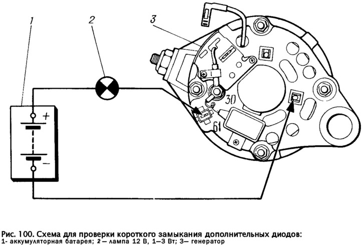
- open or short circuit («breakdown») in diodes 14 (see fig. 98), supplying the excitation winding. Check if there is «punched», diodes (passing current in both directions) can be according to the diagram in Fig. 100. In this case, it is necessary to disconnect the wires from the generator, as well as the wire from the output «IN» voltage regulator. If lamp 2 is on, then one of the diodes «broken». Find «pierced» diode, as well as a diode with a break (not passing current in both directions) It is possible, Only by disassembling the generator, removing the rectifier unit and checking each diode individually. Replace damaged diode;
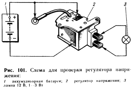
- damaged voltage regulator. Remove the voltage regulator with brush holder and check it according to the diagram in fig. 101. To conclusions «B», «IN» and to «mass» regulator, connect power supply 1, first with a voltage of 12 V, and then 15... If the lamp is on in both cases, then there is a breakdown in the regulator. A. if it does not light up in both cases, then either there is an open in the regulator, or there is no contact between the terminals of the brushes and the voltage regulator. To restore contact, clean the leads of the brushes and the voltage regulator. Replace damaged regulator;
- breakage in one or more valves of the rectifier unit. A valve with a break can only be detected by disassembling the generator and checking each valve of the block separately. Replace the rectifier unit with damaged valves with a new one;
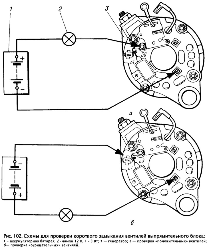
- short circuit («breakdown») in the negative valves of the rectifier unit or short circuit of the stator winding pa «mass». You can check according to the diagram in Fig. 102b. «Minus» battery 1 is attached to «mass» generator, and «plus» through lamp 2 to any bolt securing the rectifier unit. If lamp 2 is on, then either «broken» negative valve, or the stator winding is closed pa «mass». To specifically determine the cause, disassemble the generator and check with an ohmmeter if the stator winding is shorted to «mass», and separately check the negative valves of the rectifier unit. When closing pa «mass» winding, the generator stator is replaced, and when «breakdown» negative valves rectifier unit;
- open circuit or interturn circuit in the stator winding. An open circuit can be detected by checking with an ohmmeter each phase winding of the stator after disassembling the generator, and an interturn circuit can only be detected with a special device at a service station. Replace damaged stator;
- closure pa «mass» generator excitation winding leads. To check, remove the voltage regulator and an ohmmeter or use a lamp and a battery to check the resistance between the slip ring of the rotor and «weight». Repair the short or replace the alternator rotor.
b) The control lamp does not light up.
Causes of the malfunction and how to fix it:
- there is no contact between the outputs of the voltage regulator and the outputs of the brushes. Remove the voltage regulator with the brush holder, disconnect them and clean the leads of the brushes and the voltage regulator;
- wear or sticking of the brushes, oxidation of the slip rings of the rotor. Remove the brush holder with voltage regulator from the generator, check if the brushes move freely in the brush holder. If the brushes are worn out (brush protrusion less than 5 mm), then replace the brush holder with brushes. Wipe the slip rings with a cloth soaked in gasoline, and if they are badly burned, then clean them with a fine-grained sandpaper;
- damaged voltage regulator. Check the regulator according to the method described above according to the scheme shown in fig. 101. Replace damaged voltage regulator;
- wire disconnected from outlet «IN» brush holder. Check, connect the wire;
- open circuit between plug «61» generator and mounting block. The generator is not excited, because the current from the battery does not pass to the excitation winding. To check, connect the plug with a separate wire «61» with clamp «30» alternator or with terminal «plus» battery and start the engine. If the voltmeter shows normal voltage, then the brown wire with a white stripe connecting the plug is damaged «61» generator with mounting block. Check the wire and its connections, replace the damaged wire;
- short circuit («breakdown») in the positive valves of the rectifier block. You can check the diagram (pic. 102, a). «Plus» battery through lamp 2 is connected to the output «30» generator, and «minus» - to any bolt of fastening of the rectifier unit. If lamp 2 lights up, then one of the positive valves is broken and the rectifier unit must be replaced;
- soldering of the excitation winding leads from slip rings. Remove the voltage regulator and check the resistance between the contact rings with an ohmmeter. In case of a break, solder the winding leads to the slip rings or replace the generator rotor.
Generator voltage above normal
The voltmeter needle is in the red zone at the end of the scale when the engine is running.
The cause of the malfunction is damage to the voltage regulator. Check it according to the above method but the diagram in fig. 101. Replace damaged voltage regulator.
Increased generator noise
Causes of the malfunction and how to fix it:
- loosening the nut securing the alternator pulley. Tighten the nut;
- generator bearing damage. Dismantle the generator and replace the damaged bearings;
- interturn short circuit or short circuit to «mass» stator windings, short circuit in one of the rectifier unit valves. This gives rise to a characteristic «howl» generator. Check the stator and rectifier unit as described above.