
In modern front-wheel drive vehicles, axle shafts with two synchronous ball joints are used to drive the front wheels: the drive wheel has a rigid type (with angular degree of freedom), and for a power unit of a universal type (with angular and axial degrees of freedom).
The front wheel drive used on cars is compact and reliable. Its durability, with proper operation of the car, is high. This is ensured by the perfection of the design of the hinges, the selection of improved materials, the accuracy of manufacturing parts, good tightness of the hinges and the use of special lubricants.
Torque from gearbox 3 (pic. 67) it is transmitted to the front wheels through the right 1 and left 2 wheel drives, each of which consists of two hinges of equal angular velocities, and a shaft, which is made of a bar for the left wheel drive, and a pipe for the right one.
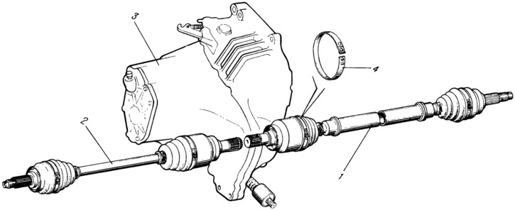
Pic. 67. Front wheel drive:
1 - drive of the right front wheel; 2 - left front wheel drive; 3 - gearbox; 4 - cover clamp.
The outer hinge consists of a body 1 (pic. 68), separator 4, inner cage 3 and six balls. Grooves are made in the hinge body and in the holder to accommodate the balls. The grooves in the longitudinal plane are made along the radius, which provides an angle of rotation of the outer hinge up to 42°. The inner cage is mounted on the splines of the shaft 9 and is held on it by a retaining ring 2. On the other side of the cage, a thrust ring 8 is installed in the groove of the shaft. To protect the internal cavity of the hinge from contamination, a corrugated protective cover 7 is attached to the hinge body and on the shaft with clamps 6 and 10. To ensure the tightness of the cover in the places of its fastening, grooves are made on the hinge body, into which the cover is pressed when the clamp is tightened. On the other hand, the grooves are made in the case itself. They create a labyrinth seal. Clamps are made of a steel band, on which three sockets and one fixing tooth are stamped. Two sockets are used for tightening the clamp with a special device, the fixing tooth of the clamp enters the third. The slotted tip of the hinge housing is inserted into the hub and fastened with a nut.
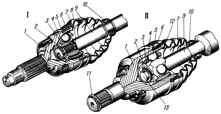
Pic. 68. Wheel drive joints:
I - external hinge; II - internal hinge;
1 - hinge body; 2 - clip retaining ring; 3 - hinge holder; 4 - separator; 5 - ball; 6 - outer collar of the cover; 7 - protective cover of the hinge; 8 - thrust ring; 9 - wheel drive shaft: 10 - inner clamp of the cover; 11 - retaining ring side gear; 12 - lock of the internal hinge; 13 - shaft buffer.
The inner hinge differs from the outer one in that the tracks for the balls both in the housing and in the cage 3 are straight rather than radial, which allows the hinge parts to move in the longitudinal direction. This is necessary to compensate for movements caused by oscillations of the front suspension and power unit. The longitudinal movement of the cage in the hinge body is limited on one side by a wire retainer 12, on the other hand, by a plastic buffer 13. The retainer is installed in the groove of the hinge body, and the buffer is installed in the end of the wheel drive shaft. The splined tip of the hinge body is connected to the side gear and fixed in it with a retaining ring 11. The hinge parts are protected from contamination by a rubber cover 7.
The parts of the outer and inner hinges are lubricated with SHRUS-4 grease, which is put into the hinges during assembly and does not change during the operation of the car if the covers ensure the tightness of the hinges,
Balls of the same sorting group are installed in the outer and inner hinges. Replacement of any one part is not allowed hinges are replaced as an assembly.