




Contents: 16-valve engines ↓ 8-valve engines ↓
Note: The timing belt should be replaced every 45,000 km on 16-valve engines and every 75,000 km on 8-valve engines.
To complete the work you will need: a hex key by 5 mm (for 16-valve engines), key by 10 mm (for 8-valve engines).

Camshaft drive diagram: 1 - toothed pulley of the engine crankshaft; 2 - lug on the oil pump cover; 3 - toothed pulley of the coolant pump; 4 - tension roller; 5 - toothed pulley of the exhaust camshaft; 6 - rear timing belt cover; 7 - toothed pulley of the intake camshaft; 8 - guide roller; 9 - toothed belt; A - TDC mark on the toothed pulley of the crankshaft; B - mark on the oil pump cover; C, F - mark on the rear timing belt cover; D - mark on the toothed pulley of the exhaust camshaft; E - mark on the toothed pulley of the intake camshaft
16-valve engines
Note: The work is shown on the 21124 engine. On the 2112 engine, the front cover is not divided into upper and lower parts.
Removal
1. Prepare the car for work (see "Preparing the car for maintenance and repair").
2. For convenience, remove the adsorber and move it to the side. Without disconnecting the hoses from it, remove the bracket that holds it.
3. With a hex key by 5 mm we unscrew the five bolts securing the upper part of the front timing belt cover.
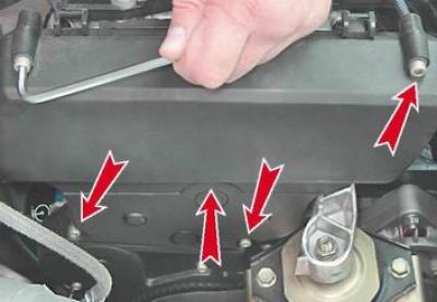
4. Remove the top part of the lid.
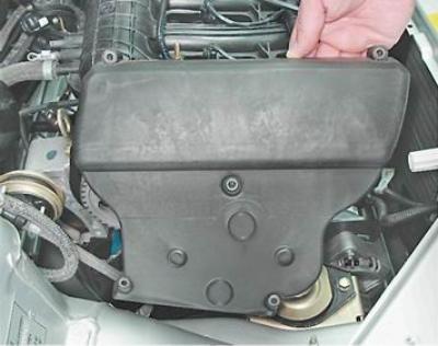
5. Using the same key, unscrew the two bolts securing the lower part of the front cover.
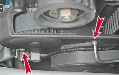
6. Remove the lower part of the front cover.
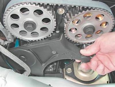
7. Remove the front right wheel (see "Wheel - replacement") and place the car on a secure stand.
8. Remove the right mudguard from the engine compartment (see "Engine compartment mudguards - removal and installation").
9. Turn the crankshaft with a socket wrench at 17 or 19 mm for the pulley mounting bolt, set the piston of the first cylinder to the TDC position of the compression stroke. In this case, the marks on the crankshaft and camshaft pulleys will align with the installation marks on the oil pump housing and the rear timing belt cover.
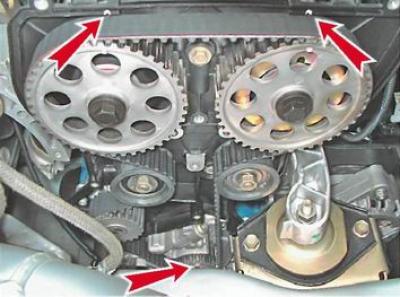
10. Remove the crankshaft pulley (see "Crankshaft pulley - removal and installation").
Note: To remove the belt, simply unscrew the tension roller nut a few turns and loosen the belt tension. However, it is easier to remove and put the belt on the pulleys when the tension roller and guide roller move freely along the studs
11. Key by 17 mm we unscrew the nuts securing the tension and guide rollers.
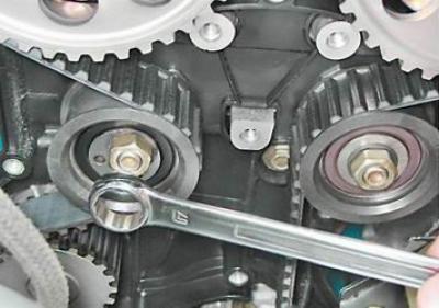
12. Remove the belt.
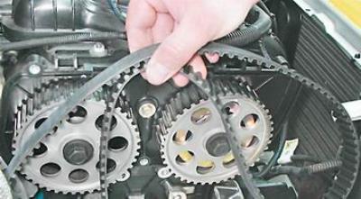
13. Rotate the tension and guide rollers to check their condition. Replace the roller that has play and makes a lot of noise when rotating.
Installation
1. Place the belt on the toothed pulley of the crankshaft, making sure that the mark on the pulley is aligned with the mark on the oil pump housing.
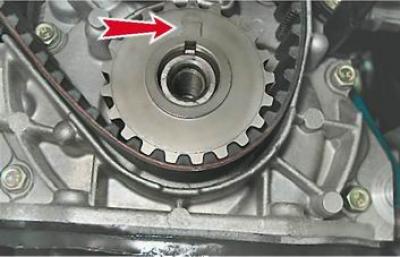
2. Pass the left branch of the belt along the outer side of the coolant pump pulley and the inner side of the tension roller. Pass the right branch along the inner side of the guide roller.
Note: If there is a device for fixing the camshaft pulleys, install it and put the belt on the pulleys, preventing sagging of its right branch and the section between the camshaft pulleys.
If there is no device, it should be taken into account that after removing the toothed belt, the camshaft pulley of the intake valves, under the action of their springs, will turn one tooth clockwise, and the exhaust valves - counterclockwise.
3. Key by 17 mm turn the inlet camshaft pulley counterclockwise until the marks on the pulley and cover align. Having removed the slack in the right-hand belt branch, place the belt on the exhaust camshaft pulley.
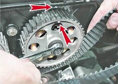
Without giving the belt the opportunity to jump over the pulley teeth, we allow the pulley to return to its original position (turn one tooth to the right).
4. Key by 17 mm we turn the exhaust valve shaft pulley, setting it in a position similar to the position of the intake valve pulley (the pulley mark is located one tooth to the right of the mark on the cover).
5. Holding the pulley in this position, we throw the belt over its upper part, preventing the belt from sagging between the pulleys and from jumping over the teeth of the intake valve pulley.
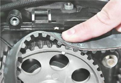
6. Turning the pulleys with a key by 17 mm, we tighten the right branch of the belt without allowing the crankshaft pulley to turn and completely put the belt on the exhaust camshaft pulley.
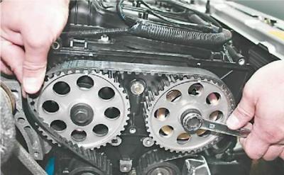
7. Check the alignment of the marks on all three pulleys in the TDC position of the compression stroke of the first cylinder (see above).
8. Tension the toothed belt (see "Timing belt - checking and adjusting tension") and tighten the roller mounting nuts.
9. Key by 19 mm using the pulley mounting bolt, turn the engine crankshaft two full turns, then again check the alignment of the crankshaft and camshaft pulley marks with the timing marks on the engine. If necessary, repeat the timing belt adjustment.
10. Install the front timing belt cover, crankshaft pulley, alternator belt and parts removed during disassembly in place.
8-valve engines
Removal
1. Prepare the car for work (see "Preparing the car for maintenance and repair").
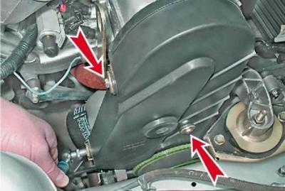
2. Key by 10 mm we unscrew the three bolts securing the front timing belt cover.

Camshaft drive diagram: 1 - toothed pulley of the engine crankshaft; 2 - toothed pulley of the coolant pump; 3 - tension roller; 4 - rear timing belt cover; 5 - toothed pulley of the camshaft; 6 - timing belt; 7 - lug on the oil pump cover; A - mark on the toothed pulley of the crankshaft; B - mark on the tide of the oil pump cover; C - protrusion on the rear timing belt cover; D - mark on the toothed pulley of the camshaft
3. Lift the cover vertically upwards, then remove it from the engine.
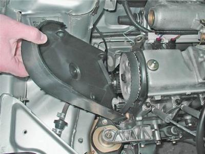
4. Remove the front right wheel (see "Wheel - replacement") and place the car on a secure stand.
5. Remove the right mudguard from the engine compartment (see "Engine compartment mudguards - removal and installation").
6. Turn the crankshaft with a socket wrench at 17 or 19 mm for the pulley mounting bolt, set the piston of the first cylinder to the TDC position of the compression stroke. In this case, the camshaft pulley mark will be aligned with the installation protrusion on the rear timing belt cover.
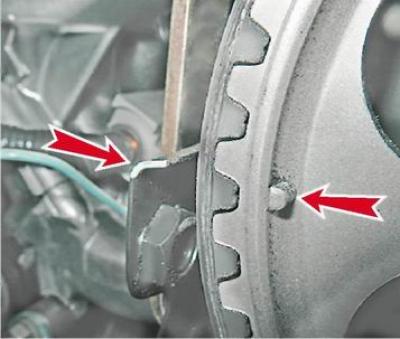
7. Remove the crankshaft pulley (see below, "Crankshaft pulley - removal and installation").
8. Unscrew the tension roller mounting nut and loosen the toothed belt tension as much as possible (see "Timing Belt - Checking Condition and Adjusting Tension").
9. Remove the timing belt from the pulleys.
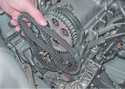
10. Rotate the tension roller to check its condition. Replace the roller that has play and makes a lot of noise when rotating.
Installation
1. Check the alignment of the marks on the toothed pulley of the crankshaft and the lug on the oil pump housing.
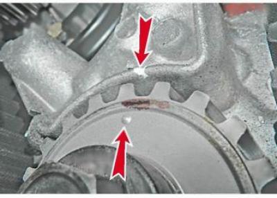
2. We also make sure that the mark on the camshaft pulley and the protrusion on the rear timing belt cover match (see above p. 4).
3. Install the new belt in the following sequence: without allowing the toothed pulleys of the crankshaft and camshaft to turn relative to the marks, put the belt on the crankshaft pulley; slightly tightening the right branch of the belt, we put it on the camshaft pulley; we pass the belt from the inside of the tension roller and put it on the coolant pump pulley.
4. Adjust the belt tension (see "Timing Belt - Checking Condition and Adjusting Tension").
5. Tighten the crankshaft pulley mounting bolt and, having turned the engine crankshaft two revolutions, make sure that the marks on the pulleys and the engine match. If necessary, reinstall the belt.
6. Install the crankshaft pulley in place and tighten the bolt
7. Install the front timing belt cover, alternator belt and parts removed during disassembly in place.