




- a special template or a wide metalworking ruler;
- set of flat feeler gauges.
Sequence of execution
1. Prepare the car for work (see "Preparing the car for maintenance and repair").
2. Remove the cylinder head (see "Cylinder head of engines 2112 and 21124 (16v) - removal and installation", or see. "Cylinder head of engines 2111 and 21114 (8v) - removal and installation").
3. We clean the cylinder head and bearing housing from dirt and carbon deposits, wash it from oil deposits, and remove carbon deposits from the walls of the combustion chambers with a metal brush.
4. Carefully inspect the cylinder head and bearing housing. There should be no cracks on them. There should be no burrs or traces of metal drag on the working surfaces of the camshaft supports, on the bearing housings and on the walls of the valve tappet seats.
The valve guides and seats should fit tightly in the head body, without any signs of displacement during the operation of the timing system. The valves and their seats should not have cracks or signs of burning. We check the valve play in the guides, the maximum permissible gap is 0.30 mm.
5. Check the flatness of the head. We carry out the work in two stages.
Note: The work is shown on the example of the cylinder head of a 16-valve engine; on the cylinder head of an 8-valve engine it is performed similarly.
This requires a special template, but if you don't have one, you can check the lower mating plane of the head with sufficient accuracy using a wide metalworking ruler.
We apply the ruler with its edge diagonally to the plane of the head. We make sure that there is no gap between the edge of the ruler and the plane of the head. The gap can be observed both in the middle part of the plane and at its edges. We measure the gap along both diagonals with a set of flat feeler gauges.
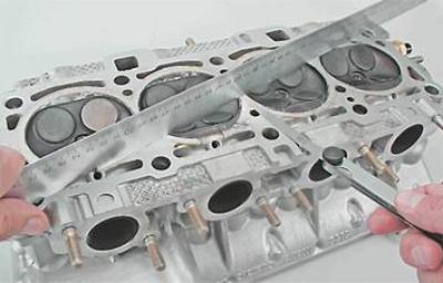
The maximum allowable gap is 0.1 mm.
If the gap is greater than the permissible value, the head must be milled along the mating surface or replaced.
Warning! The cylinder head of a 16-valve engine should only be replaced complete with the bearing housing.
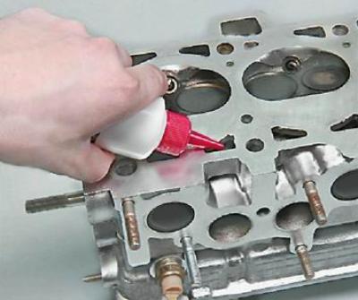
6. Check the tightness of the cylinder head. To do this, close the window of the coolant supply channel to the thermostat with a plug on the end surface of the cylinder head.
7. Turn the head over and fill its internal cavities for coolant with kerosene.
Note: The check is shown using the example of the cylinder head of an 8-valve engine. On a 16-valve engine, it is carried out similarly.
8. We check the tightness of the valves (see below, "Valves - grinding").