
Comment. The work is shown on the engine 21124. See the text for details of the work on the engine 2112.
Removing
1. We prepare the car for work (see "Preparing the car for maintenance and repair").
2. Remove the camshaft pulleys (see "Camshaft pulleys - removal and installation").
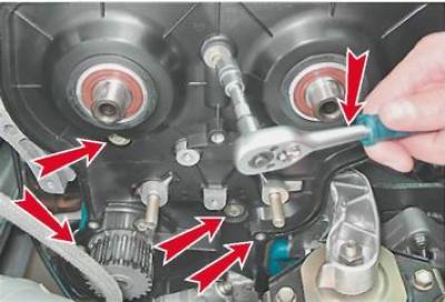
3. Remove the tension and guide rollers (see "Timing belt - replacement").
4. socket wrench by 10 mm unscrew the six bolts securing the rear timing belt cover and remove it.
5. Remove the cylinder head cover (see "Cylinder head cover for 2112 and 21124 engines (16v) - removal and installation").
6. In order not to damage, remove the oil pressure sensor (see "Emergency oil pressure sensor in the engine - replacement") or disconnect the wire tip from it.
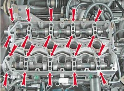
7. socket wrench by 8 mm evenly, half a turn, unscrew the 20 bolts securing the camshaft bearing housing.
8. Remove the camshaft bearing housing.
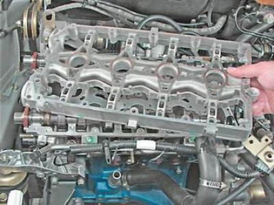
Comment.On the 2112 engine, remove the camshaft bearing housing together with the spark plug guide tubes (candle wells). We remove the pipes from the bearing housing.
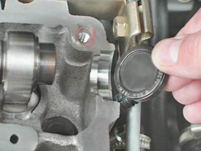
9. We take out two plugs of technological holes from the seats in the head of the block (near the rear ends of the camshafts).
10. Remove the intake and exhaust camshafts.
11. Remove the seals from the shafts.
12. We examine the shafts. On the necks and cams of the shaft, there should not be signs of heavy wear, scratches, cracks, traces of metal enveloping.
Installation
1. Lubricate the bearing journals and shaft cams with clean engine oil.
2. We put the camshafts in the cylinder head. Shafts are not interchangeable and have different markings.
The exhaust valve shaft is marked 1006014.
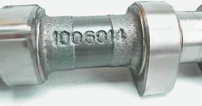
The intake valve shaft is marked 1006015.
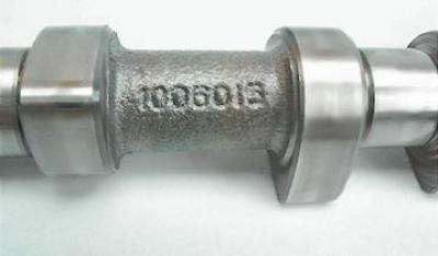
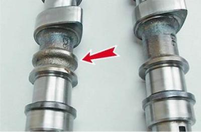
In addition, the intake valve shaft has an additional belt.
Attention! When repairing the engine, do not use a sealant with a high content of silicone (silicon compounds), whose vapors can get through the crankcase ventilation system into the cylinders and further into the exhaust tract. Use a sealant specifically labeled as safe for the oxygen sensor
Attention! Do not apply too much sealant to the mating surfaces of the bearing housing. When tightening the mounting bolts, the sealant squeezed into the internal cavities of the engine can clog the oil channels.
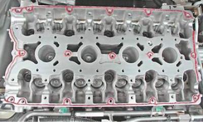
3. We apply a thin layer of sealant on the plane of the cylinder head and on the lower surface of the bearing housing around the holes of the candle wells "Loctite" No. 574 or similar according to the following scheme:
4. We install the camshafts in the cylinder head with the keyways up.
5. We install the bearing housing on the cylinder head and evenly tighten the bolts of its fastening until the bearing housing contacts the cylinder head. We finally tighten the bearing housing mounting bolts in pairs, with a torque of 8.0-10.0 N·m (0.8-1.0 kgf·m) in the following sequence (see photo).
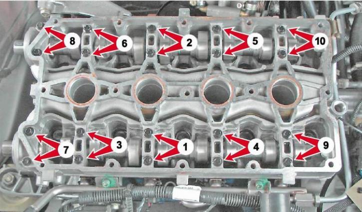
Camshaft bearing bolt tightening sequence
6. We press in the camshaft seals (see "Camshaft seals - replacement").
7. On the engine 2112 apply clean engine oil to the rubber o-rings of the spark plug guide tubes (candle wells) and install the pipes in the head.
8. Further assembly is carried out in the reverse order of disassembly.