




Contents: Removal ↓ Installation ↓
To perform the work you will need a piston ring mandrel and a torque wrench.
Removal
1. Prepare the car for work (see "Preparing the car for maintenance and repair").
2. Remove the cylinder head (see "Cylinder head of engines 2112 and 21124 (16v) - removal and installation", or "Cylinder head of engines 2111 and 21114 (8v) - removal and installation").
3. Remove the engine oil pan (see "Engine oil pan - removal and installation, gasket replacement").
4. Remove the oil intake (see "Oil intake - removal and installation").
5. Turn the crankshaft by the bolt securing its pulley with a wrench at 17 or 19 mm, we set the piston of the first cylinder to the lower position.
Warning! When loosening the connecting rod cap nuts on engines with an oil level sensor, there is a high risk of damaging it, so we recommend removing the sensor first (see "Oil level sensor - replacement").
6. With a socket wrench by 14 mm we unscrew the two nuts securing the connecting rod cover.
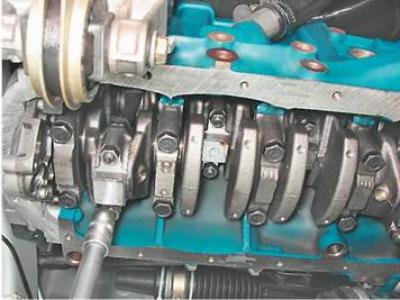
Warning! When disassembling the connecting rod, do not press out the bolts from it.
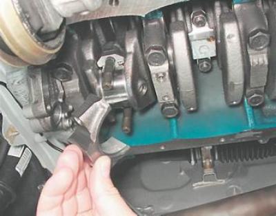
7. Remove the connecting rod cover.
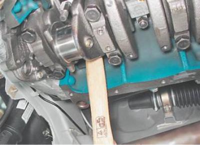
8. Press the hammer handle against the piston and push it upward.
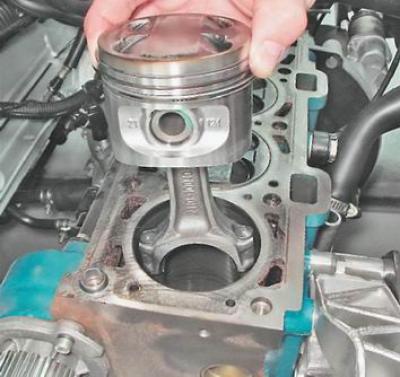
9. Remove the piston from the cylinder.
10. Remove the liners from the connecting rod and its cover.
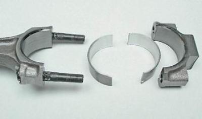
Warning! The advisability of replacing the liners depends on the degree of wear of the crankshaft journals (see "Cylinder block - checking technical condition, removal and installation").
11. Fix the piston assembly with the connecting rod by the connecting rod in a vice.
12. Slightly moving the ring lock apart, remove the upper compression ring.
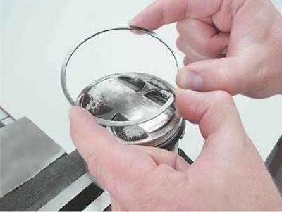
13. Remove the lower compression ring in a similar manner.
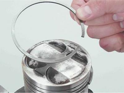
14. Remove the oil scraper ring...
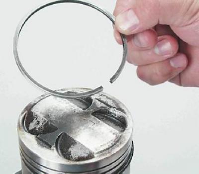
...and its expander.
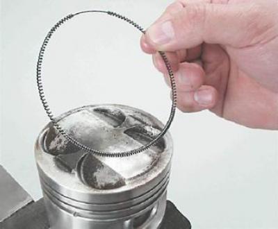
Warning! The advisability of replacing the rings depends on the degree of wear of the cylinders (see "Selection of pistons for block cylinders").
Installation
1. Carefully clean the piston from carbon and deposits. Inspect the piston, connecting rod and pin. Cracks on them are unacceptable.
2. New rings are selected in accordance with the diameter of the piston of the nominal or repair size. There are no markings on the rings of the nominal size, repair rings are increased in diameter by 0.4 or 0.8 mm and are marked "40" and "80" respectively.
Recommendation: To install new rings on the piston, we recommend using a special piston ring puller.
3. Before installing new rings, use a set of feeler gauges to measure the gap between the piston ring and the wall of the groove into which the ring will be installed.
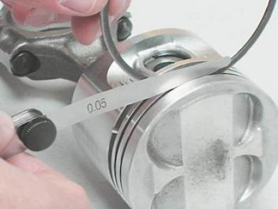
Table 8.3. Permissible clearance in the piston ring groove
|
Ring |
Gap between ring and groove wall, mm |
|
Upper compression ring |
0,04-0,075 |
|
Lower compression ring |
0,03-0,065 |
|
Oil scraper ring |
0,02-0,055 |
If the gap exceeds the maximum allowable value, the piston must be replaced.
Oil scraper ring...
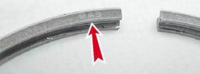
...and we install the upper compression ring with the inscription "VAZ" or "TOR" facing up.
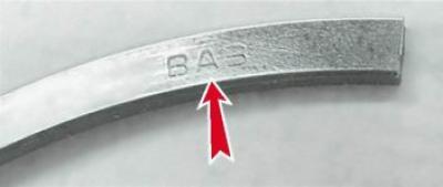
We orient the lower compression ring so that its groove is directed downwards.
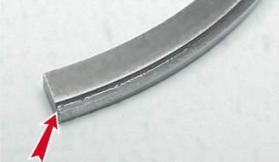
4. We put the rings on the piston as follows: by moving the ring lock apart (no more than is required to put the ring on the piston), we first place the lock on the piston, and then the back part of the ring.
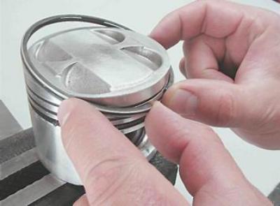
We install new rings on the piston, starting with the oil scraper ring expander. After installing the oil scraper ring, the expander lock should be turned 180° relative to the ring lock.
After installing the rings on the piston, we turn their locks so that the lock of the upper compression ring is located at an angle of 45° to the axis of the piston pin, the lock of the lower compression ring is turned by 180°, and the lock of the oil scraper ring by 90° relative to the lock of the upper compression ring.
5. Lubricate the piston, rings and cylinder wall with fresh engine oil.
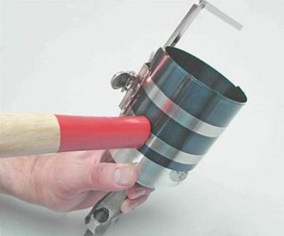
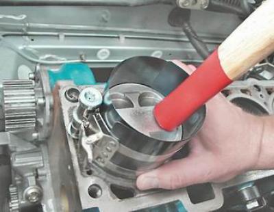
6. Place the mandrel on the piston and use it to compress the rings, periodically tapping the mandrel lightly with the hammer handle to ensure the rings are self-installing.
7. Wipe dry the bearing beds in the connecting rod and cover and install the bearings in the lower head of the connecting rod.
(The article is copied from the website: «vazbook»)
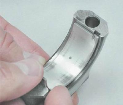
8. Lubricate the inner surface of the liners and the crankshaft connecting rod journal with clean engine oil. Turning the crankshaft, move the journal to the extreme lower position.
9. Install the piston on the block and orient it so that the arrow on the bottom of the piston is directed towards the crankshaft pulley.
10. Pressing the mandrel against the block and tapping the bottom of the piston with the hammer handle, we press it into the cylinder, while simultaneously monitoring the movement of the connecting rod toward the crankshaft journal.
11. Install the cover on the connecting rod and tighten the nuts to a torque of 43.32-53.5 N·m (4.42-5.46 kgf·m).
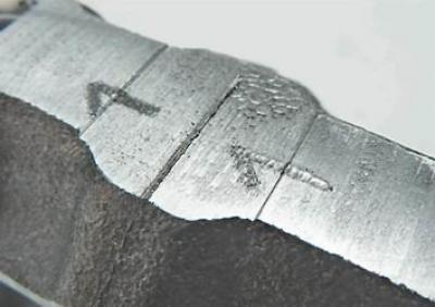
Warning! Connecting rod caps are not interchangeable. The connecting rod and its cap indicate the cylinder number in which the connecting rod should be installed. On the assembled connecting rod, the numbers should be located on the same side.
We replace the rings of the other three pistons in the same way.
After installing all the pistons, we assemble the engine in the reverse order.