
To check, assemble the circuit according to Fig. 7-6. Disconnect the common terminal wire of the three additional diodes from the plug «IN» voltage regulator and take care that the tip of the disconnected wire does not short-circuit with «weight» generator. To plug «IN» regulator, connect the wire from the battery through the control lamp 1. Thus, the excitation winding will be powered only from the battery.
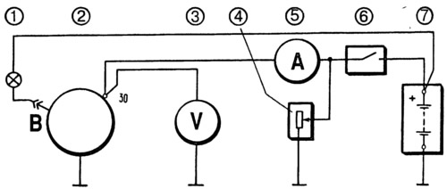
Pic. 7-6. Connection diagram for checking the generator with an oscilloscope:
1 - control lamp 12 V, 3 W; 2 - generator; 3 - voltmeter; 4 - rheostat; 5 - ammeter; 6 - switch; 7 - battery.
Turn on the electric motor of the stand and bring the rotor speed up to 1500-2000 min-1. Use switch 6 to disconnect the battery from the output «30» generator and rheostat 4, set the output current to 10 A.
Check the voltage on the oscilloscope «30» generator. With serviceable valves and stator winding, the rectified voltage curve has a sawtooth shape with uniform teeth (pic. 7-7, I). If there is an open in the stator winding or an open or short circuit in the valves of the rectifier unit, the shape of the curve changes dramatically: the uniformity of the teeth is disturbed and deep cavities appear (pic. 7-7, II and III).
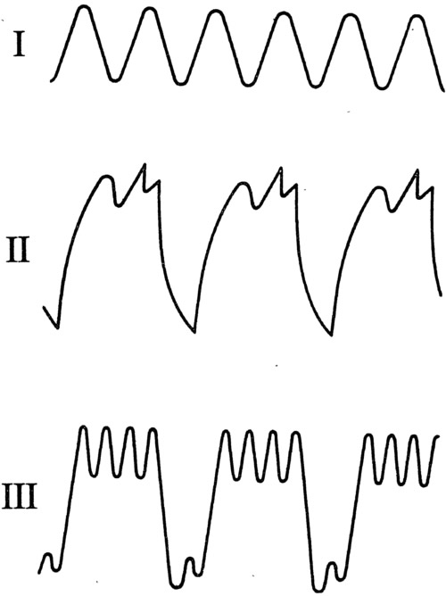
Pic. 7-7. Generator rectified voltage waveform:
I - the generator is working; II - the valve is broken; III - break in the valve circuit (stator winding).
By checking the shape of the voltage curve at the output «30» generator and making sure that it has a normal appearance, check the voltage on the plug «61» or on the tip of a wire disconnected from the plug «IN» voltage regulator. These points are the common terminal of three additional diodes (rice. 7-4), supplying the excitation winding during the operation of the generator. The shape of the voltage curve here should also have a regular sawtooth shape. An irregular shape of the curve indicates damage to the additional diodes.