
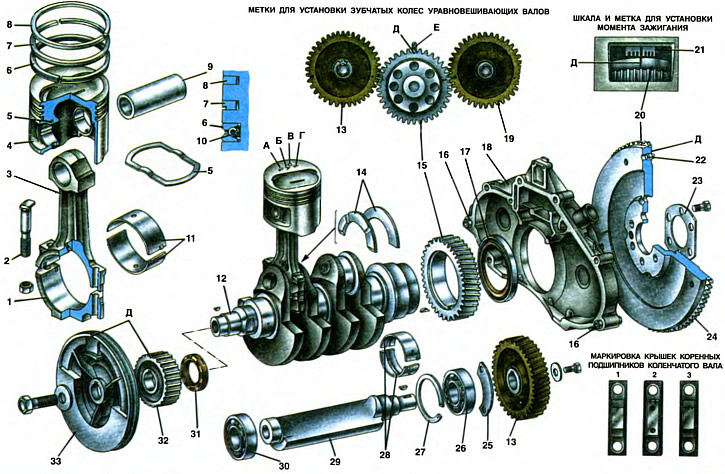
1. Connecting rod cap. 2. A bolt of fastening of a cover of a rod. 3. Connecting rod. 4. Piston. 5. Piston thermostatic plate. 6. Oil scraper ring. 7. Lower compression ring. 8. Top compression ring. 9. Piston pin. 10. Expanding spring (expander). 11. Connecting rod bearing shells. 12. Crankshaft. 13. Left balance shaft gear. 14. Thrust half rings. 15. Balance shaft drive gear. 16. Centering sleeve. 17. Rear crankshaft oil seal. 18. Rear oil seal holder. 19. Right balance shaft gear. 20. Flywheel. 21. Scale on the holder 18 of the rear oil seal. 22. Clutch locating pin. 23. Washer of bolts of fastening of a flywheel. 24. Gear rim flywheel. 25. Thrust half ring of the bearing. 28. Rear bearing. 27. Retaining ring. 28. Inserts of the radical bearing. 29. Left balance shaft. 30. Front bearing. 31. Front crankshaft oil seal. 32. Camshaft drive gear pulley.
A. Piston category marking by piston pin bore
B. Piston class marking by outer diameter
B. Piston oversize marking
D. Setting pointer
D. Mark c. m.t. pistons
E. Label on the cylinder block
The crank-slider mechanism is used to convert the translational movement of the piston into the rotational movement of the crankshaft. The mechanism consists of a piston 4 with piston rings 6, 7 and 8 and a pin 9, a connecting rod 3, a crankshaft 12 and a flywheel 20. Details of the crank-slide mechanism are located and operate in the cylinder block. The crankshaft is the main power part of the engine, which perceives the loads of gases and inertia forces of reciprocating moving parts and transmits them through the flywheel to the vehicle's transmission converted into torque.
Details of the piston group and other parts of the crank mechanism are subjected to significant mechanical and thermal loads. The selection of materials for the piston, pin, piston rings and their design provide reliable sealing of the cavities of the combustion chamber and cylinder, efficient heat dissipation, minimum friction coefficient, high strength and reliability with a low weight of parts.
Piston
Piston 4 is cast from a high-strength aluminum alloy. The aluminum piston is light and conducts heat well to the cooled cylinder walls. But aluminum has a high temperature coefficient of linear expansion. Therefore, in order to impart thermal deformation of the piston during heating in the desired direction and to eliminate the risk of piston jamming in the cylinder, a temperature-controlled steel plate 5 is poured in the piston head above the hole for the piston pin.
To ensure the established clearance between the cylinder mirror and the piston, pistons and cylinders are sorted by mating diameter into five classes: A, B, C, D and E. Piston class (letter) stamped on its bottom. The letters represent the following dimensions (in mm) piston diameter: A-75.965...75.975; B-75.975...75.985; C-75.985...75.995; D-75.995...76.005; E-76.005...76.015.
It is necessary to measure the piston diameter to determine its class in a plane perpendicular to the piston pin at a distance of 51.5 mm from the bottom. In other places, the piston diameter differs from its nominal diameter, since the outer surface of the piston has a complex shape. It is oval in cross section (ovality of the piston head from 0.1 mm, and skirts up to 0.55 mm), and the smaller axis of the oval coincides with the axis of the piston pin. In height, both the skirt and the piston head have a conical shape and, in addition, the diameter of the head is 0.5 mm less than the diameter of the skirt. This shape of the piston at room temperature provides the most favorable shape of the piston when working in the engine cylinder.
The outer surface of the piston skirt is not smooth, but has a number of annular microgrooves up to 14 microns deep. Such a surface contributes to a better running-in of the piston and a reduction in friction between the piston and the cylinder, since oil is retained in the micro-grooves. The bottom of the piston is flat, with an oval recess for the combustion chamber and small recesses for the valves. In the lower part of the bosses under the piston pin there are holes for the passage of oil to the piston pin. To improve lubrication conditions, two longitudinal grooves 3 mm wide and 0.7 mm deep are made in the upper part of the finger holes, in which oil is retained. In the area of the bosses, the height of the skirt is reduced to prevent rubbing against the piston of the crankshaft counterweights.
The axis of the hole for the piston pin is shifted by 1.2 mm from the diametral plane of the piston towards the location of the engine valves. Due to this, the relocation of the piston within the gap between the skirt and the cylinder mirror when changing the direction of movement in the area of the top dead center at the beginning of the stroke occurs practically without impact. However, this requires that the piston be installed in the cylinder during assembly so that the arrow D on its bottom points towards the front of the engine.
The pistons in an engine must be of the same mass to reduce vibration due to the difference in masses of the reciprocating parts. Therefore, during manufacture, the mass of the pistons is maintained with a maximum deviation of±5 g.
By weight, the pistons are sorted into three groups: normal, increased by 5 g and reduced by 5 g. These groups correspond to the markings on the piston crown: «G», «+» and «—» On the engine, all pistons must be of the same mass group.
Spare parts are supplied with nominal size pistons of only three classes: A, C and E. This is enough to match the piston to any cylinder during engine operation, since pistons and cylinders are divided into classes with some overlap in size. For example, a class C piston can fit class B and D cylinders. The main thing when choosing a piston is to provide the necessary mounting clearance between the piston and the cylinder of 0.025... 0.045 mm.
In addition to pistons of nominal size, repair pistons with an outer diameter increased by 0.4 and 0.8 are also supplied as spare parts. These pistons are intended for installation in overhauled cylinder blocks, in which the cylinders are bored and honed to the next repair size. On the bottoms of the repair pistons, marking B is placed in the form of a square or triangle. A triangle corresponds to an increase in the outer diameter of 0.4 mm, and a square corresponds to 0.8 mm.
There are three annular grooves on the piston head: compression rings 7 and 8 are installed in the upper two, and an oil scraper ring 6, equipped with an expanding spring 10, is installed in the lower one. cylinder, goes inside the piston and «drains into the engine crankcase.
Piston pin
Piston pin 9, pivotally connecting the piston to the upper head of the connecting rod, steel with an internal hole, is pressed into the upper head of the connecting rod with an interference of 0.010... 0.042 mm and rotates freely in the piston bosses (gap 0.008 - 0.016 mm).
Pins by outer diameter, as well as pistons by the diameter of the hole for the pin, are sorted through 0.004 mm into three categories. Categories are indicated by a number (1, 2, 3) on the bottom of the piston and paint on the end of the finger: blue - the first category, green - the second, red - the third. The assembled pin and piston must belong to the same category, such selective assembly ensures that the required clearance is obtained. Correct mating can be checked by inserting an oiled finger into the piston. The pin should be easily inserted into the piston by hand pressure and not fall out of the piston under its own weight.
Piston rings
Piston rings 6, 7 and 8 provide the necessary sealing of the cylinder, remove part of the heat perceived by the piston head to the cylinder wall and distribute the oil film on the surfaces of the skirt and cylinder, preventing oil from entering the combustion chamber. The rings are made of cast iron, they are pressed against the cylinder wall by their own forces. elasticity and gas pressure, and ring 6 additionally with spring 10.
The upper compression ring 8 operates under conditions of high temperature, aggressive effects of combustion products and insufficient lubrication, therefore, to increase wear resistance, the outer surface is chrome-plated and has a barrel-shaped generatrix to improve running-in.
The lower compression ring 7 has a groove at the bottom for collecting oil during the downward stroke of the piston, while performing the additional function of an oil drop ring. The surface of the ring is phosphated to increase wear resistance and reduce friction against the cylinder walls.
The oil scraper ring 6 has on the working surface between two chrome-plated support belts an annular mass-collecting groove and there are four holes in it for draining the oil removed from the cylinder walls. The ring thus has two scraping edges.. This spring, acting on the ring, increases the uniformity of the radial pressure on the cylinder, without interfering with the freedom of movement of both the ring and the piston.
Repair rings are made (just like pistons) with an outer diameter increased by 0.4 and 0.8.
Connecting rod
Connecting rod 3 is the part that connects the piston to the crankshaft. When the engine is running, alternating loads from the forces of inertia and gas pressure act on the connecting rod. Dynamic loads on the connecting rod at the moment of ignition of the working mixture in the combustion chamber require that, with a minimum weight, the connecting rod has high rigidity, resistance to shock loads, and sufficient fatigue strength.
For this, the connecting rod is made of forged steel and consists of an I-section rod, an upper one-piece and a lower split head. In the lower head of the connecting rod with a cover 1, liners 11 of the connecting rod bearing are installed, which mates with the connecting rod journal of the crankshaft. The diametral clearance between the neck and the connecting rod bearing shells is 0.02... 0.07 mm.
The cover of the lower head of the connecting rod is fastened with two bolts 2 with self-locking nuts. To ensure the centering of the bolts, their outer surface and the hole in the connecting rod are machined with high precision, and the bolt head has a belt with which the bolt is pressed into the hole. To ensure accuracy, the hole for the liners in the lower head of the connecting rod is machined complete with a cover. In order not to confuse the connecting rod covers during assembly, the connecting rod and the corresponding cover are stamped with the number of the cylinder in which they are installed. When assembling, the numbers on the connecting rod and cap must be on the same side. Until 1997, at the point of transition of the lower head of the connecting rod to the rod, there was a hole through which oil was sprayed onto the cylinder walls.
When assembling the connecting rod and piston group, the connecting rods with the said hole must be positioned so that the hole on the connecting rod and the arrow on the piston bottom are directed in the same direction. Connecting rods without a hole can be connected to the piston in any position.
To ensure engine operation without vibration, the mass of both connecting rods assembled with covers is adjusted by removing metal from the side bosses on the upper head of the connecting rod and from the boss on the cover so that the mass of the upper heads of the connecting rods differs by no more than±2 g, and the lower ones - by no more than±3 g.
Crankshaft
The crankshaft 12 is cast from high-grade special cast iron and consists of connecting rod and main polished journals, jaws and counterweights. To reduce the deformation of the shaft during engine operation, it is made tricycle and with a large overlap of the main and connecting rod journals. The high fatigue strength of the crankshaft material is ensured by structurally smooth transitions between the journals and cheeks and careful processing of stressed areas. The high wear resistance of the shaft journals is achieved by their large diameter, which reduced the specific loads in the bearings, and by surface hardening of the journals with high-frequency currents to a depth of 2...3 mm.
The diameter of the main journals of the crankshaft is 50.799... 50.819 mm, the diameter of the connecting rod journals is 47.83... 47.85 mm.
To reduce the load from centrifugal forces on the main bearings and reduce engine vibration, the shaft is equipped with counterweights cast in one piece with it. The counterweights partially balance the centrifugal forces acting on the connecting rod journals from the movements of the connecting rod with the piston that occur during engine operation. With the help of dynamic balancing of the crankshaft, the unbalance value in the plane passing through the middle of the first main journal is 19782±50 g mm, and the third - 21376±50 g mm.
Channels are drilled in the body of the shaft connecting 1 and 3 main journals with connecting rods. Oil is supplied through these channels to lubricate the connecting rod bearings. Technological outlets of the channels are closed with cap steel plugs, which are pressed into the channels and minted at three points. The oil outlet for lubrication of each connecting rod bearing is carried out in two places through a horizontal through channel in the corresponding neck, which contributes to uniform wear of the necks around the circumference.
The diametral clearance between the main journal and the main bearing shells is 0.026... 0.073 mm.
It is possible to regrind the crankshaft journals during repairs with a decrease in diameter.
At the front end of the shaft, equipped with an oil seal 31, the toothed pulley of the camshaft drive 32 and the generator drive pulley 33 are bolted to the key. a flywheel 20 with a gear rim 24 is fixed. The flywheel is equipped with clutch locating pins 22, and on the outer surface it has a mark c. m.t. pistons (mark D). The rear shaft seal is fixed in the rear seal holder 18, which is centered on the block by centering bushings 16.
Balancing mechanism
The balancing mechanism consists of two balancing shafts 29 located in the cylinder block on both sides of the crankshaft. The shafts are cast iron and have an unbalance equal to 5679.9±50 g mm in the plane of the front support, and 4906±50 g mm in the plane of the rear support. This amount of unbalance is provided by drilling holes from the outer surface of the balance shaft during its dynamic balancing.
The shafts rotate in two ball bearings 26 and 30 installed in the seats of the cylinder block. The drive of the left and right shafts is carried out from the drive gear 15, mounted on a key at the rear end of the crankshaft. The driven gears 13 and 19 of the shafts are also mounted on keys.
For the balancing shafts to work effectively, it is necessary that the forces of inertia from the masses of pistons with connecting rods and from the unbalanced masses of the balancing shafts be directed in opposite directions and mutually compensate each other. This is ensured by the exact installation of the balancing shafts relative to the crankshaft according to the marks on the gears.