
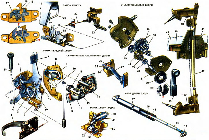
1. Interior front door handle. 2. Roller off the lock. 3. Central roller. 4. The lever of blocking of the lock. 5. Thrust of the button of blocking of the lock. 6. The lever of the internal drive of the lock. 7. External drive lever. 8. The body of the latch of the lock. 9. Retainer cracker. 10. Lock rotor. 11. Leash of the lock switch. 12. External lock drive button. 13. door lock switch. 14. The body of the external drive of the lock. 15. Mounting bracket. 16. Support washer. 17. Ratchet. 18. Lock lever. 19. Hood lock hook. 20. The hood lock rotor. 21. Hood latch. 22. Thrust drive lock. 23. Drive handle. 24. Door stopper roller. 25. Buffer. 26. Rusk. 27. Rod. 28. Window handle. 29. Facing window handle. 30. Rosette. 31. Lead roller. 32. Brake spring driver. 33. Brake spring. 34. Support of the leading roller. 35. Drive gear. 36. Cable. 37. Drum with gear rim. 38. Sliding glass. 39. Clip of glass. 40. Window regulator rollers. 41. Plate. 42. Guide tube. 43. Hinge finger. 44. Stock. 45. Stem seal. 46. Piston. 47. Stop cylinder. 48. Lock button. 49. Push button. 50. Spike of the castle. 51. Retainer socket. 52. Lock hook.
Hood lock
The hood lock is fastened with two nuts to the welded bolts of the upper cross member of the front end. The body of the lock is stamped from sheet steel. At the top, in the middle part, the body has a special cutout for fixing the latch pin 21, welded to the hood, and holding the hood from transverse displacements. A lock rotor 20 and a lever 18 are installed on the body on the axes, which are pulled together by one spring.
When the hood is closed, the latch 21 on the hood presses the rotor 20, sinking it down and stretching the spring. The rotor captures the latch pin, and with its upper edge engages with the tooth of the lever 18 and fixes the hood in the closed position.
When acting on the handle 23 of the drive, the wire rod 22, which is in a plastic sheath, pulls the lever 18 and unlocks the lock, freeing the rotor. Under the action of a spring, the rotor 20 raises the hood above the surface of the body. The handle 23 of the lock drive is mounted on a bracket under the instrument panel.
To protect against spontaneous opening of the hood, a hook 19 for blocking the hood with a handle and a spring is installed on the lock body, which presses the hook towards the rotor 20. The hook 19 holds the hood by the latch 21 when the lock is open. To open the hood, lift the handle of the hook 19, moving it to the side and releasing the latch 21.
Adjustment of the hood lock is carried out by shifting the lock to the desired position, provided by enlarged oval holes in the lock body for reliable locking and unlocking of the lock.
Rotary front door lock
The teeth of the rotor 10 mounted on the central shaft 3, when the door is closed, run into the tooth of the body 8 of the latch and turn the shaft 3 with the ratchet 17. The protrusion of the lever 7 of the external drive, under the action of the spring, stops the shaft with the rotor and the ratchet. Ratchet teeth provide preliminary and full locking of the lock. Pre-locking prevents spontaneous opening of the door in case of accidental incomplete closing. Incomplete closing is easy to determine by the knock of the rotor 10 on the housing 8 of the latch or by the existing movement of the door when it is pulled up.
When opening the door, the button 12 of the external drive is pressed, which with its rod presses on the upper end of the lever 7 and releases the ratchet. From the impact of the compressed seal, the door opens. The external drive housing is installed through the seal on the outer door panel and fastened with bracket 15.
When opening the door with the inner handle 1, its thrust acts on the two-arm lever 6 of the internal drive, which presses the lever 7, releasing the ratchet, and the door opens.
The lock can be locked with a button to prevent access to the interior from the outside. When the lock button is pressed with the door closed, the rod 5 rotates the provided spring-loaded lock lever 4, which blocks the external drive lever 7 with its groove. The locked front door lock can be released: by lifting the lock button in the passenger compartment, by pulling the interior handle 1 or by using the lock switch 13.
When the switch key 13 is turned, the leash 11 of the latter acts through the rod, the roller 2 on the lever 4 of the lock lock, blocking or releasing the lever 7 of the external drive.
On the door locks next to the rotor 10 there is a special support washer 16, which, when the door is closed, comes into contact with the cracker 9 of the latch, which is pressed by the spring. The retainer key selects the gap between the upper edge of the support washer and the retainer body and eliminates the vertical «game» doors while driving. In the event of a collision or rollover of the vehicle, the support washer 16 simultaneously prevents the doors from spontaneously opening due to its deformation or deformation of the body pillars. The support washer extends beyond the walls of the housing 8 of the latch and prevents such movement of the lock.
The lock body is fastened rigidly with screws to the end of the door, the lock retainer is bolted to the central pillar of the body. To ensure normal preload of the door seals and avoid the door falling or protruding relative to the surface of the body, as well as in height to ensure the normal closing of the door, the latch can be displaced in the transverse direction by increasing the holes in the rack.
Front door opening limiter
The limiter for opening the front door does not allow contact with the front pillar when opening it. The limiter consists of a steel flat rod 27, the front end of which is pivotally fixed with a finger in the lugs of a plate attached with screws to the front pillar of the body. The rod passes through the door opening and the limiter body attached to it. The rear end of the rod has a pin with a support washer that limits the maximum opening of the door. The rod has vyshtampovki on both sides. To the rod 27 are pressed two steel rollers 24, which are inserted into the cracker 26, made of polyamide. A rubber buffer 25 is installed under the support washer of the rod. In the open position, the door is held by rollers 24 for the punching of the rod 27.
Power window door
The door window regulator is cable-operated, mounted on the inner panel of the door. The window regulator consists of a window regulator mechanism and a guide tube 42 with upper and lower brackets equipped with rollers 40. The rollers 40 cover the cable 36. In the mechanism housing, the cable is wound on a drum 37 with a driven gear, in engagement with which is the drive gear 35. The hub of the drum with the driven gear is installed in two plastic bushings inserted into the holes of the housing and cover. The ends of the rope are fixed on a plate 41 which can move along the guide tube 42.
The drive roller 31 is equipped with a spring brake. The deformation of the spring 33 of the brake in the support 34 prevents spontaneous lowering of the glass 38.
The handle 28 of the power window is installed on the splines of the drive shaft 31 and is fixed to it with the help of the facing 29 of the handle, which, when the handle is installed, stops it by the annular groove of the shaft. A plastic socket 30 is installed under the handle, pressed by the door upholstery.
When turning the handle 28, the cable moves the plate 41, raising or lowering the glass 38, the holder 39 of which is fixed with two bolts to the plate 41.
This design of the power window eliminates the need for adjustment. When operating the car, only checking the fastening of the window lifter parts is required.
Tailgate stops
The tailgate stops are designed to hold the door in the open position. The stops are gas-filled, attached to the body and the door with pins 43 with ball heads. The threaded ends of the fingers are screwed into the weld nuts of the tailgate and body brackets. A piston 46 is inserted into the cylinder 47 of the stop, the rod 44 of which exits through the stuffing box 45, which seals the internal cavity of the cylinder. The stop is located with the cylinder up. The piston and cylinder are lubricated with brake fluid «Neva». Gas is loaded into the cylinder (nitrogen) under pressure 60 kgf/cm2. As a result of this, the stop is not allowed to be disassembled, and if it fails, it must be replaced.
Tailgate lock
The tailgate lock is attached to the inner panel of the door, the lock retainer is attached to the body. The lock consists of a housing in which are located: a hook 52 with a spring, a button 48, locked with a key, and a button spring. The hook of the lock engages with the latch tooth.
To prevent vibration of the tailgate, the lock has a special spike 50, which, when the door is closed, enters the conical socket 51 in the upper part of the latch.
Enlarged holes in the latch for fastening screws allow you to adjust the position of the latch, which ensures reliable locking of the door lock.
Outside rearview mirror
Outside rear view mirror (see ch. 1 pos. 19) located on the front door. The glass of the mirror is held in a stamped housing by a plastic frame. To set the mirror in a position convenient for viewing from the driver's seat, the mirror housing is pivotally connected to the handle in the passenger compartment.
The mirror housing can be rotated on the hinge axis and displaced beyond the dimensions of the vehicle. The necessary tension of the hinge is provided by a spring. The inner surface of the mirror is pasted over with a film so that when it hits the mirror, there is no injury from glass fragments.
Interior rear view mirror
Interior rear view mirror (see ch. 1 pos. 7) located above the middle of the windshield. To set the mirror to a position convenient for viewing from the driver's seat, it can be adjusted on a spherical joint, as well as switched to a position that eliminates the blinding of the driver by the light of the headlights of the vehicle behind.
In the normal position of the housing, light passes through the wedge-shaped glass of the mirror and, reflected from the inner mirror surface, enters the driver's eyes. When blinded by bright light, the driver removes the switch handle, while the mirror housing turns, and the outer plane of the glass becomes the place previously occupied by the mirror surface. The bright light from the mirror is shifted, and the driver's eyes are hit by weak light reflected from the glass.