
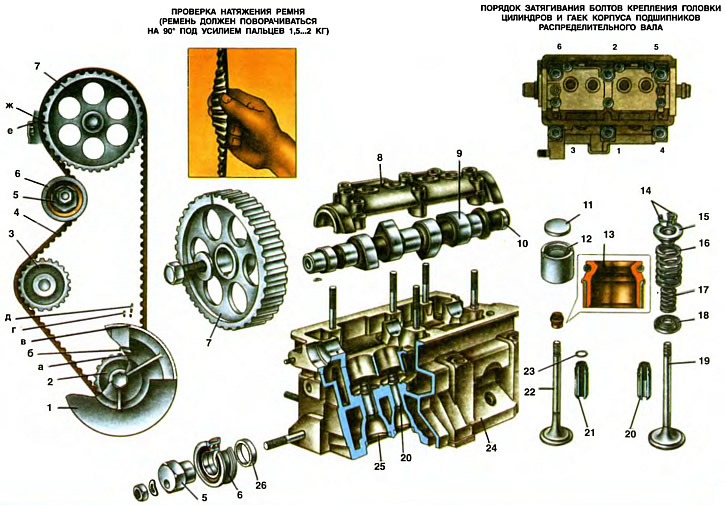
1. Generator drive pulley. 2. Camshaft drive pulley. 3. Coolant pump pulley. 4. Camshaft timing belt. 5. Eccentric axis of the tension roller. 6. Tension roller. 7. Camshaft pulley. 8. Camshaft bearing housing. 9. Camshaft. 10. Eccentric on the camshaft to drive the fuel pump. 11. Adjusting washer. 12. Valve lifter. 13. Oil cap. 14. Valve crackers. 15. Valve spring plate. 16. Outer valve spring. 17. Internal valve spring. 18. Support washer springs. 19. Inlet valve. 20. Intake valve guide. 21. Exhaust valve guide. 22. Exhaust valve. 23. Retaining ring. 24. Cylinder head. 25. Valve seat. 26. Distance ring.
a - label c. m.t. pistons on a toothed pulley
b - installation mark on the cover of the oil pump
c - mark c. m t pistons on the generator drive pulley
g - ignition advance mark by 5°on the front cover of the toothed belt
e - ignition timing mark ka 0°on the front cover of the toothed belt
e - installation mark (tendril) on the back cover of the toothed belt
g - alignment mark on the camshaft pulley
Gas distribution mechanism
The gas distribution mechanism ensures that the engine cylinders are filled with a fresh charge of the combustible mixture and the exhaust gases are released in accordance with the requirements of the working process in each of the engine cylinders. This mechanism is characterized by an upper in-line arrangement of valves.
The camshaft 9, which controls the opening and closing of the valves, is located in the cylinder head 24 and is driven from the crankshaft by an elastic toothed belt 4 with 111 teeth. Valves 19 and 22 are actuated directly by the camshaft cams via cylindrical valve tappets 12, without intermediate levers. In the pusher seat there is an adjusting washer 11, by selecting which the clearance in the valve drive mechanism is adjusted.
The toothed belt also drives the pulley 3 of the coolant pump. Tension roller 6 serves to tension the belt. It rotates on the eccentric axis 5 of the tension roller, attached to the cylinder head on a stud through a spacer ring 26. By turning the axis 5 relative to the attachment stud, the belt tension is changed. The belt tension is considered normal if, in the middle part of the branch between the pulleys of the camshaft and crankshaft, the belt is twisted 90°with a finger force of 1.5... 2 kgf. If the force is below normal, loosen the nut of the tension roller, turn its axis by the hexagonal head by 10... 15°counterclockwise and tighten the axle nut. Turning the crankshaft clockwise for the bolt securing the alternator drive pulley two turns, check the belt tension. If the tension is not enough, then the belt tensioning operation is repeated. The nut for fastening the tension roller axle is tightened with a torque of 4 kgf·m. Do not allow excessive tension on the belt, as this will significantly reduce its service life.
Since 1989, instead of a toothed belt with semicircular teeth, a belt with grooves on the tops of the teeth has been used (trapezoidal teeth). Accordingly, the profile of the troughs on the toothed pulleys has also changed. These belts are fully interchangeable, i.e. a belt with grooves on the teeth can be installed on pulleys with semicircular cavities and vice versa.
Since 1996, a tension roller 6 with a plastic rim has been installed. Moreover, it is installed without axis 5 directly on the stud, and the distance ring has other dimensions (outer diameter 28 mm, inner diameter 10.1 mm and thickness 7±1 mm). When adjusting the belt tension, the roller is turned with a special key with two pins that fit into two holes on the inner ring of the roller.
The pulley 7 of the camshaft drive and the pulley 3 of the coolant pump are made by pressing from sintered metal. Toothed pulley 2 camshaft drive (leading) has 21 teeth, is keyed at the front end of the crankshaft. Pulley 7 camshaft (slave) has 42 teeth, is mounted on a key at the front end of the camshaft and secured with a bolt and washer.
Due to a certain orientation of the keyways in the driving 2 and driven 7 pulleys relative to the teeth and their corresponding engagement with the toothed belt, the required valve timing is provided. Checking the correct relative position of the drive pulleys is carried out as follows: the crankshaft rotates clockwise to the position at which the piston of the first cylinder is in c. m.t. compression stroke (both valves are closed, and the mark is in. m.t. pistons on pulley 1 of the crankshaft generator drive is aligned with mark b on the oil pump cover). In this case, the mark w must coincide with the mark e on the back cover of the toothed belt, and the mark on the flywheel must be against the middle division of the scale on the holder of the rear crankshaft oil seal (see ch. 9).
If the marks do not match, then loosen the belt with a tension roller, remove pulley 7 from the camshaft, correct the position of this pulley, put the belt on the pulley again and slightly tighten it with a tension roller. Again, check the coincidence of the alignment marks by turning the crankshaft two turns clockwise.
Turn the crankshaft only with the camshaft drive belt installed and only by the bolt of the generator drive pulley in the direction of tightening the bolt (clockwise). It is not allowed to turn the crankshaft by the camshaft pulley or its fastening bolt.
When laying the camshaft in the cylinder head bearings 24, the position of the cams of the camshaft 9 of the first cylinder must correspond to the closed state of both valves, and the crankshaft must be in position c. m.t. compression stroke of the first cylinder (mark a is aligned with mark 6).
When installing pulley 7, also make sure that cage w on the pulley is approximately opposite the alignment mark e on the rear toothed belt protection cover. The permissible mismatch is no more than two pulley teeth, otherwise the valves of the fourth cylinder will rest against the piston. For this reason, it is also not allowed to turn and rotate the camshafts and crankshafts before installing the belt.
Camshaft
Camshaft 9, cast iron, has three bearing journals with a diameter of 24.931... 24.915 mm, which rotate in sockets. Made in the cylinder head 24 and housing 8 camshaft bearings. Holes for camshaft bearings with a diameter of 25,000... 25,025 mm are machined in the cylinder head assembly with the camshaft bearing housing, which ensures high accuracy, the correct geometric shape of the holes and their alignment. On the camshaft there is an eccentric 10 for the fuel pump drive. The rear end of the camshaft has a groove for connection to the spark torque sensor of the engine ignition system.
From axial movements, the camshaft is held by a thrust shoulder of the shaft, located between the end of the rear shaft support and the housing of auxiliary units. A gap of 0.15... 0.53 mm between the thrust shoulder of the shaft in the rear bearing seat and the end face of the seat belt of the auxiliary unit housing, determined by the difference in the thickness of the shoulder and the depth of the groove in the rear support closed by the housing, ensures free rotation of the shaft.
To increase wear resistance, the working surfaces of the eccentric cams and the surface of the camshaft journal under the oil seal are bleached. The depth of the bleached layer is not less than 0.2 mm. The hardness of the cams and the eccentric is not less than 50 units on the scale «WITH» Rockwell instrument (HRC>50).
Valves
valves (intake 19 and exhaust 22), which serve to periodically open and close the openings of the intake and exhaust channels, are located in the cylinder head obliquely in one row. The intake valve head has a larger diameter for better cylinder filling, and the exhaust valve face, which operates at high temperatures in an aggressive exhaust gas environment, has a heat-resistant alloy overlay. In addition, the exhaust valve is made of composite: the stem is made of chromium-nickel-molybdenum steel with better wear resistance to friction and thermal conductivity to remove heat from the valve head to its guide sleeve, and the head is made of heat-resistant chromium-nickel-manganese steel. The inlet valve is made of chrome silicon steel.
The diameter of the valve stems is 7.985...8.00 mm, the angle of the working chamfer is 45°30'.
The outer diameter of the intake valve head is 35 mm (37 mm for engine 11113), and exhaust - 31.5 mm.
Guide bushings
The guide bushings of the inlet 20 and exhaust 21 valves are made of cast iron, pressed into the head with an interference fit of 0.063...0.108 mm and are held from possible falling out by retaining rings 23. The holes in the bushings are finally machined complete with the cylinder head, which ensures a small diameter tolerance holes and the accuracy of its location in relation to the working chamfers of the seat and valve.
The bores of the guide bushings have spiral grooves for lubrication. The inlet valve bushings 20 are grooved up to half the length of the bore, and the exhaust valve bushings 21 are grooved along the entire length of the bore.
The outer diameter of the bushings is 14.040...14.058 mm, the inner diameter is 8.022...8.040 mm at the inlet valve bushing and 8.029...8.047 at the exhaust valve bushing.
Oil deflector caps 13 made of fluororubber rubber with a steel reinforcing ring are put on top of the guide bushings, which cover the valve stem and serve to reduce the penetration of oil into the combustion chamber through the gaps between the guide bushing and the valve stem.
Springs
Springs (outer 16 and inner 17) press the valve against the seat and do not allow the valve lifter to come off the actuator. The lower ends of the springs rest on the support washer 18 springs. The upper support plate 15 of the valve springs is held on the valve stem by two crackers 14 of the valve, having a truncated cone shape when folded. The crackers have three inner collars that fit into the corresponding grooves on the valve stems. This design provides both a reliable connection and the ability to rotate the valves during operation, so that they wear more evenly.
Pushers
Valve tappets 12 are designed to transfer force from the camshaft cams to the valves. The pushers are made in the form of cylindrical cups with a diameter of 35.275... 35.295 mm and are placed in the guide slots of the cylinder head with a gap of 0.025... 0.070 mm. An adjusting washer 11 of a certain thickness is placed in the end recess of the pusher, providing the necessary clearance between the camshaft cam and the pusher with the washer. Washers 11 are made of steel 20X and subjected to nitrocarburizing, which provides a hardness of their surface of 58 units on a scale «WITH» Rockwell instrument (58 HRC).
When the engine is running, due to the displacement of the contact zone with the cams by 1 mm relative to the axis, the pushers rotate around their axes, which ensures uniform wear along the outer diameter.