
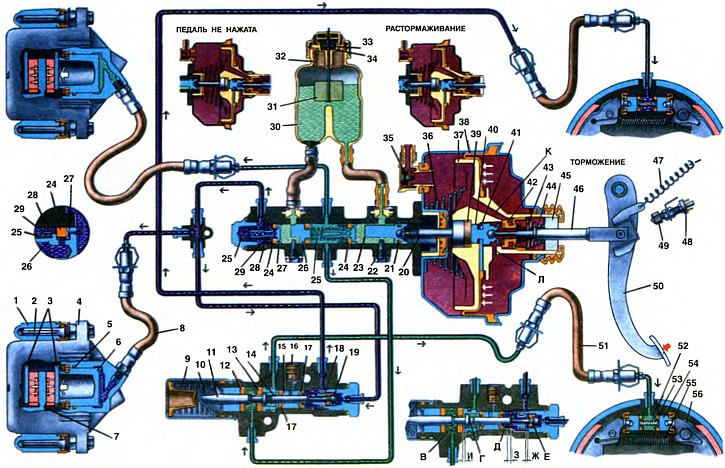
1. Shoe guide. 2. Guide pin. 3. Front brake pads. 4. Caliper with cylinder. 5. Piston O-ring. 6. Wheel cylinder piston. 7. Disc brake. 8. Front brake hose. 9. Spring. 10. Spring stop. 11. Pressure regulator piston. 12. Piston sealing ring. 13. Piston head seal. 14. Pusher. 15. Pusher bushing. 16. Plug. 17. Pusher sealing ring. 18. Valve seat. 19. Pressure regulator valve. 20. Vacuum booster rod. 21. Low pressure sealing ring. 22. Limit screw. 23. Circuit drive piston «right front - left rear brakes». 24. High pressure sealing ring. 25. Piston return spring. 26. Circuit drive piston «left front - right rear brakes». 27. Piston spacer. 28. O-ring retainer spring. 29. Cup. 30. Master cylinder reservoir. 31. Float. 32. Reflector. 33. Moving contact. 34. Fixed contact. 35. Vacuum valve. 36. Valve body return spring. 37. Valve body. 38. Diaphragm. 39. Buffer. 40. Vacuum booster piston. 41. Thrust plate. 42. Vacuum booster valve. 43. Valve spring. 44. Valve return spring. 45. Air filter. 46. Pusher. 47. Brake pedal return spring. 48. Stoplight switch. 49. Tip of the brake light switch. 50. Brake pedal. 51. Rear brake hose. 52. Spacing spring for wheel cylinder pistons. 53. Piston seal. 54. Rear brake wheel cylinder piston. 55. Coupling spring pads. 56. Brake shoe.
A - vacuum cavity
B - atmospheric cavity
K and L - channels
C, D, D and F - pressure regulator chambers
G, 3 and I - gaps
Service brake system
The brake mechanisms of the wheels are driven by a hydraulic drive, which is controlled by the brake pedal. Depending on the position of the pedal, the following components of the working process of the brake system are distinguished: the system is disinhibited, braking, releasing.
The system is broken. In the initial position, the brake pedal 50 is pulled by the spring 47 until it stops at the tip 49 of the brake light switch 48, the contacts of which open the circuit of signal lamps.
The valve pusher 46, and with it the valve body 37 with the stem 20, are pressed by the return spring 36 to the rearmost position (in the direction of the car). Piston 40 is pressed against the end of valve 42, blocking the access of atmospheric air to cavity B. Vacuum cavity A through channels K and L freely communicates with atmospheric cavity C. Therefore, when the engine is running, vacuum is transmitted through vacuum valve 35 to cavity A and through channels K and L - in cavity B.
The pistons 23 and 26 of the main cylinder under the action of the return springs 25 are pressed to the rearmost position until they stop against the limit screws 22. The spacer rings 27, resting against the limit screws, press the seals from the ends of the grooves, opening passages for the brake fluid. The cavities of the master cylinder freely communicate with the cavities of its reservoir and both brake circuits. Thus, there is no fluid pressure in the brake actuator.
The pistons of the 6 wheel cylinders of the front brakes are pressed away from the brake pads due to the elastic deformation of the sealing rings 5. The brake pads, not experiencing pressure from the pistons, remain only in light contact with the friction surfaces of the brake disc.
Due to the lack of pressure in the hydraulic circuits, the head of the piston 11 of the pressure regulator under the force of the spring 9 is pressed from the seal 13 and abuts against the pusher 14, moving the valve 19 through it, which moves away from its seat 18. In this case, gaps I and G are formed. Through the formed gaps of the chamber B and E are connected to chambers D and E.
The pads 56 of the brake mechanisms of the rear wheels are pressed from the brake drums by the force of the coupling springs 55, and under the action of the same force the pistons 54 of the wheel cylinders are pushed into the cylinders.
Braking
When the car is moving with the engine running, vacuum is created in cavities A and B of the vacuum booster. transmitted from the engine intake pipe through a hose. When you press the brake pedal 50, it moves away from the tip 49 of the brake light switch, and the control lamp circuit is closed. At the same time, the pusher 46 moves along with the piston 41 of the vacuum booster. Following the piston, the valve 42 moves under the force of the spring 43 until it stops in its seat; in this position, the cavities A and B of the amplifier are separated. The piston 40 of the valve, moving forward, moves away from the valve 42, and a gap is formed between the piston and the end of the valve, through which cavity B is connected to the atmosphere. Filling the vacuum, outside air enters through channel L into cavity B, creating pressure on the valve body 37 through the diaphragm 38. This reduces the force required for braking on the brake pedal from the driver's side.
The pressure developed on the valve body depends on the vacuum in the engine intake pipe and on the force applied to the brake pedal.
Together with the body 37 of the valve, the stem 20 also moves. Initially, the gap between the piston 23 and the adjusting bolt of the stem is selected. Its value corresponds to the free travel of the brake pedal 3... 5 mm. After selecting the gap, the rod moves the piston 23 forward. The spacer ring 27 moves away from the restrictive screw 22, and the seal is pressed against the end of the piston groove, i.e., the cavities of the main cylinder and the reservoir are separated. From this point on, with further advancement of the piston of the drive circuit «right front and left rear» brake mechanisms, fluid pressure builds up. At the same time, under the pressure of the liquid in this circuit, the piston 26 of the circuit drive begins to move «left front - right rear» brakes. Under increasing fluid pressure, the high pressure rings 24 expand and fit more tightly to the cylinder face and groove ends, which improves the sealing of the pistons in the cylinder.
From the main brake cylinder, fluid pressure is transmitted to chambers B and E of the pressure regulator and through gaps I and G to the wheel cylinders of the rear brake mechanisms. With an increase in fluid pressure, the force on the piston 11 of the regulator increases, tending to push it out of the housing. When the force from the fluid pressure exceeds the force from the spring 9, the piston begins to move out of the housing, and after it the valve 19 and the pusher 14 move under the action of the spring. At a pressure of 3.5±0.5 MPa (35±5 kgf/cm2) gaps H and W are selected completely. A further increase in pressure in chamber D will be carried out when the fluid is throttled between the piston collar 11 and seal 13. and in the chamber - when the sleeve 15 is displaced under the action of pressure in the chamber G. After choosing gaps I and G, the pressure at the regulator outlet increases to a lesser extent and determined by the ratio of the areas of the shoulder and the piston rod.
If the brake drive circuit fails «left front - right rear» O-rings 17, bushing 15 under fluid pressure in chamber G will shift towards the plug until clearance 3 is selected. The pressure in the rear brake will be regulated by the part of the pressure regulator, which includes piston 11 with seal 13, piston bushing with retaining ring, spring 9 with stop 10 and stop cup. At the same time, the operation of this part of the regulator in the event of a failure of the named circuit is the same as in the case of a working system.
In case of circuit failure «right front - left rear» there is no pressure in chamber B. Due to the pressure of the liquid in the chamber D, the pusher 14 and the piston 11 are displaced, overcoming the force of the spring 9. Since the cross-sectional area of the pusher 14 is less than the cross-sectional area of the piston rod 11, the clearance G will be selected at a higher pressure than with a working system. The regulator will work as a pressure limiter at the level of 6...7 MPa (60...70 kgf/cm2).
Under the pressure of the brake fluid, overcoming the elastic deformation of the sealing rings 5, the pistons 6 move out of the cylinders and press the inner brake pads 3 against the disk 7, and the wheel cylinders with calipers 4 (movable brackets) move in the opposite direction under the force of the resulting reaction. Movable calipers press the outer brake pads against the brake disc 3.
At the same time, under the pressure of the liquid, the pistons in the wheel cylinders of the rear brake mechanisms move apart, overcoming the resistance of the coupling springs 55 of the pads. The pads are pressed against the brake drums, creating a braking torque on the wheels. At the moment of touching the drum pads, they self-install on the supports.
If, during braking, the driver stops pressing the brake pedal, leaving it pressed in some position, then the valve body of the vacuum booster will move forward under the pressure of atmospheric air by the amount of the gap between the stop plate 41 and the piston groove 40. In this case, the released end of the valve 42, having reached to the end of the piston 40, will block the flow of atmospheric air into cavity B, and the excess air will pass into the vacuum cavity A through the newly opened slot in the valve seat, channel K and further into the engine inlet pipe. The pressure in both cavities will equalize, and the servo action of the amplifier will stop. The brake mechanisms of the wheels for some period of time will maintain a constant braking torque on the wheels.
Release
When the brake pedal is released, it returns to its original position by the force of the spring 47 and pulls the pusher 46 with the piston 40. The piston, touching the end of the valve 42, closes the access of atmospheric air to the cavity B. The end of the valve moves away from its seat in the valve body and opens the passage, which communicates cavity B with cavity L through channel K. The servo action of the amplifier stops, and the brake pedal, the valve body, together with the stem, are returned to their original position by the force of the return spring 36. Not experiencing pressure from the vacuum booster rod, the pistons 23 and 26 of the main cylinder under the action of the return springs 25 move back to their original position until they stop against the limit screws 22. When returning, the spacer rings 27, resting against the limit screws, retract the sealing rings to the front wall of the annular the grooves of the pistons, and the cavities of the master cylinder and reservoir communicate with each other.
The front brake pistons are retracted to the non-working position under the action of the elasticity of the sealing rings 5, and the rear brake pistons - by the contraction of the coupling springs 55 of the pads. Excess brake fluid flows through the expansion gaps into reservoir 30 of the master cylinder.
Due to the drop in fluid pressure in the hydraulic drive, the pressure regulator piston returns to its original position under the action of the spring. In this case, the piston head moves away from the seal, and the valve - from its seat. Through the formed gaps I and G, chambers E and C communicate with chambers D and D.
Parking brake system
The parking brake is activated by moving the lever 11 (see ch. 28) up. In this case, the latch 12 jumps over the teeth of the sector, and the lever 11 pulls both rear cables 14 through the rod and the equalizer 13. The force from the cables is transmitted to the levers 20 (see ch. 27) manual drive pads. The lever 20 presses on the expansion bar 21 and through it presses the brake shoe 17 to the drum. Further rotation of the lever 20 on the axis of the bolt 22 stops, and it begins to rotate relative to the point of contact with the spacer bar 21. In this case, the upper arm of the lever moves the rear brake shoe until it stops against the drum.
When the parking brake lever is lifted, its stop moves away from the control pump switch, and the pump circuit closes.
To release the brake, press the lever button to raise the latch 12 through the rod and disconnect it from the gear sector, after which the lever is lowered. The emphasis of the lever presses on the rod of the control lamp switch, and it goes out. The details of the manual drive of the pads return to their original position, and the brake mechanisms of the rear wheels are released.