




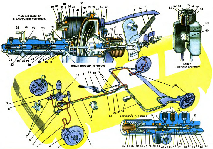
1. Brake pedal. 2. Brake disc. 3. Caliper assembly with cylinder and pads. 4. Front brake hose. 5. Pressure regulator. 6. Tee. 7. Pipe fastening bracket. 8. Brake master cylinder. 9. Brake master cylinder reservoir. 10. Vacuum booster. 11. Parking brake drive lever. 12. Lever latch. 13. Cable equalizer. 14. Parking brake cable. 15. Rod adjusting bolt. 16. Piston of drive of "right front - left rear brake" circuit. 17. Piston limit screw. 18. Spacer sleeve. 19. High-pressure sealing ring. 20. Sealing ring spring. 21. Piston return spring. 22. Thrust washer. 23. Piston of the actuator of the "left front - right rear brake" circuit. 24. Master cylinder housing plug. 25. Union. 26. Lock washer. 27. Sealing gasket. 28. Spring support cup. 29. Low pressure sealing ring. 30. Vacuum valve tip. 31. Vacuum valve. 32. Sealing flange. 33. Vacuum booster housing. 34. Rod seal collar. 35. Rod seal. 36. Valve housing return spring. 37. Rod. 38. Rod buffer. 39. Vacuum booster valve housing. 40. Diaphragm. 41. Vacuum booster housing cover. 42. Piston thrust plate. 43. Brake and clutch pedal bracket. 44. Valve piston. 45. Vacuum booster housing cover seal. 46. Vacuum booster valve. 47. Protective cap. 48. Air filter. 49. Valve tappet. 50. Brake pedal return spring. 51. Brake light switch. 52. Fixed contact. 53. Movable contact. 54. Terminal device housing. 55. Pusher for checking the serviceability of the fluid level monitoring device. 56. Reservoir cover. 57. Contact device housing. 58. Reflector. 59. Retaining ring. 60. Float. 61. Rear brake hose. 62. Rear wheel brake mechanism. 63. Pressure regulator housing plug. 64. Valve spring. 65. Pressure regulator valve. 66. Valve seat. 67. Spring. 68. Spring support cup. 69. Tappet sealing ring. 70. Tappet bushing. 71. Tappet. 72. Washer. 73. Housing bushing. 74. Piston head seal. 75. Piston sealing ring. 76. Piston bushing. 77. Pressure regulator piston. 78. Spring stop. 79. Piston spring. 80. Spring cup. 81. Support ring. 82. Protective cap. 83. Rod. 84. "Right front - left rear brake" circuit line. 85. Pipeline of the "left front - right rear brake" circuit. 86. Bracket. 87. Plug.
A - vacuum cavity
B - atmospheric cavity
B and E are the cavities of the pressure regulator connected to the master cylinder
G and D are the cavities of the pressure regulator, connected to the wheel cylinders of the rear brakes
The car is equipped with two types of braking systems - service and parking. The first serves to regulate the speed of the car and stop it with the necessary efficiency, and the parking brake system keeps the car motionless relative to the road.
The service brake system has a hydraulic drive with a diagonal division of circuits, one of which activates the brake mechanisms of the right front and left rear wheels (pos. 84), the other - the left front and right rear wheels (pos. 85). The diagonal drive is combined with a negative shoulder of rolling of the front wheels (see "Front suspension"). This drive scheme ensures the maintenance of linear motion and sufficient braking efficiency when one of the circuits is depressurized. In this case, the operating circuit will act as a backup braking system.
The parking brake system has a mechanical drive to the brake mechanisms of the rear wheels. In addition to its main purpose, the parking brake system can be used as an emergency brake when one or both circuits of the service brake system fail.
The hydraulic drive of the service brake system includes a vacuum booster 10 and a pressure regulator 5 of the rear brakes. The booster creates comfort when driving the car by reducing the force on the brake pedal and reducing the pedal travel. The pressure regulator prevents the rear wheels from locking before the front wheels are locked. It operates at a certain pressure, and its action does not depend on the load on the rear axle of the car, unlike previous VAZ models.
A number of units of the working brake system are unified with other models. For example, the vacuum booster is used from the VAZ-2103 car, the main brake cylinder is from VAZ-2121, the main cylinder reservoir is from the VAZ-21011, the front and rear hoses are from the VAZ-2108. A number of brake drive and brake mechanism parts are also unified.
The drive of the service brake system includes: brake pedal 1, vacuum booster 10, master cylinder 8 and its reservoir 9, pressure regulator 5 of the rear brakes, wheel cylinders of the brake mechanisms of the front and rear wheels and pipelines of the diagonal circuits.
Pedal 5 (see chapter 18) brake serves to drive the vacuum booster. It is suspended together with the clutch pedal from bracket 1 by means of axle 6. Two plastic bushings 30 with a diagonal cut are installed in the pedal hubs, through which an axle passes, common to both pedals. The pedal bushings are lubricated with Litol-24 grease during assembly, and do not require additional lubrication during vehicle operation. The brake pedal is installed on the axle between the cheek of bracket 1 and the spacer bushing 31. The pedal axle is fixed in the bracket holes by a locking clamp 8.
The brake pedal is set to its initial position by the release spring 50. In this position, the pedal rests against the plastic stop of the brake light switch 51. The brake pedal is pivotally connected to the pusher 49 of the vacuum booster valve. The connecting pin is fixed in the pusher hole by a locking bracket.
Vacuum booster
The vacuum booster is attached to the clutch and brake pedal bracket plate with four studs and nuts. A rubber gasket is installed between the vacuum booster and the bracket plate.
Between the vacuum booster body and its cover, the outer belt of the rubber diaphragm 40 is clamped, dividing the booster into vacuum A and atmospheric B cavities. The vacuum cavity is connected to the engine intake pipe via a hose with a tip 30 and valve 31. To seal the connection, tip 30 is connected to the vacuum booster via rubber flange 32.
Inside the vacuum booster there is a plastic valve body 39, the tail of which is sealed by a seal 45 at the outlet from the booster body. It is installed in the socket of the booster body cover and is pressed against the flange of the socket by a spacer ring, which is locked by a locking ring. To protect the movable tail of the valve body from contamination, a corrugated protective cover 47 is put on the flanged part of the booster body cover and on the tail of the valve body.
The valve body contains a buffer 38, a piston 44 with a pusher 49, a rubber valve 46, springs with support cups and an air filter 48.
A thrust plate 42 enters the groove of piston 44, the other end of which rests against the belt of diaphragm 40, which prevents it from falling out. This plate fixes the piston in the valve body 39 in assembly with the pusher 49 and valve 46. The rod 37 of the piston drive of the main cylinder rests against the buffer 38. At the exit from the vacuum booster body, the rod is compressed by a seal 35, which is pressed by a collar 34 to the socket of the booster body. A bolt 15 is screwed into the end hole of the rod, which regulates the exit of the rod from the booster body (1.25-0,2 mm) The ball head of the valve tappet is compressed in the piston seat 14.
The rubber valve 46 is assembled on the pusher 49. The movable head of the valve, reinforced with a metal washer, is pressed by a spring through the support cup to the rear end of the piston (when fully released). For the movable head of the valve in the housing 39 there is a seat. The fixed flange of the valve is pressed by a spring through the support cup to the inner wall of the valve housing tailpiece, creating a reliable seal. To clean the atmospheric air, a foam air filter 48 is installed in the valve housing tailpiece. The housing 33 and the cover 41 of the amplifier are connected to each other by inserting the projections of the cover into the recesses of the housing and then turning the cover until its edges are inserted under the projections of the housing. The joint of the cover and the amplifier housing is sealed by the flange of the rubber diaphragm 40, clamped between them.
A plastic tip 30 is attached to the amplifier body through a rubber flange 32, into which a vacuum valve 31 is mounted. It prevents the flammable mixture from entering the vacuum cavity A of the amplifier.
The performance of the vacuum booster can be checked on the car without removing it. To do this, press the brake pedal 5...6 times with the engine off to create the same pressure in cavities A and B, close to atmospheric. Keeping the brake pedal pressed, start the engine. With a working vacuum booster, the brake pedal should "go forward" after starting the engine.
If the brake pedal does not "go forward", check the fastening of the hose tip, the condition and fastening of the tip flange in the booster, the hose to the tip and the nipple of the engine intake pipe, since loosening of the fastening or damage to them sharply reduces the vacuum in cavity A and the efficiency of the booster.
Master cylinder
The main cylinder is attached to the vacuum booster body with a flange on two studs. Inside the cylinder there are two pistons: front 23 and rear 16. The front piston serves to drive the "left front - right rear brake" circuit, the rear one - to drive the "right front - left rear brake" circuit. A plug 24 with a sealing gasket is screwed into the end of the cylinder body. Between the plug and the piston, as well as between both pistons, springs 21 are installed, which return the pistons to their original position. The return stroke of the piston under the action of the springs is limited by screws 17, the tails of which enter the grooves of the pistons. The length of the groove of each piston corresponds to their maximum stroke.
In the rear bore of piston 16 and in its annular groove, sealing rings 19 and 29 are located. The front part of piston 16 passes into a shaped tailpiece, which is a guide for return spring 21. In the tailpiece, there is a central drilling, which connects to the annular groove through two radial holes. The liquid passing through the central drilling and radial holes exerts pressure on the inner surface of the front sealing ring 19, which ensures a tighter fit of the ring to the cylinder mirror.
The force from the spring 20 acts on the front sealing ring 19, tending to press the sealing ring against the end face of the piston groove. The other end of the spring rests against the support cup 28. The spacer sleeve 18 is freely placed on the piston groove.
The rear sealing ring of the front piston is pressed against the end surface of the piston by spring 21 through support washer 22.
For reliable sealing, the outer diameter of the sealing rings is slightly larger than the inner diameter of the cylinder. The shape of the rings, rounded on the side of the cylinder mirror, ensures minimal friction resistance and quite satisfactory lubrication of the sliding surface.
The piston 16 of the cavity of the "right front - left rear brake" circuit differs in its design from the piston 28 of the cavity of the "left front - right rear brake" circuit by its rear part, in which an annular groove is machined to accommodate the low-pressure sealing ring 29.
There are openings made in the cylinder body on top. Plastic fittings 25 are inserted into the bore of two of them and fixed with lock washers 26. Sealing gaskets 27 are installed under the flanges of the fittings.
Pipeline fittings of both circuits are screwed into the threaded holes.
The brake fluid reservoir is made of translucent plastic, allowing you to check the fluid level without removing the reservoir cap. It is attached to the mudguard bracket of the body with a clamp in the engine compartment under the hood.
The lower part of the tank is divided by a partition into two cavities. This ensures independent supply of brake fluid to each of the two circuits. The filler neck of the tank has a thread onto which the cap 56 is screwed.
On the neck of the tank, under the lid, there is a plastic housing 57 of the contact device with contacts 52 and 53 and a rubber reflector 58, which does not allow liquid to penetrate to the contacts.
A pusher 55 passes through the opening of the housing 57, at the upper end of which there is a movable contact 53, and at the lower end there is a float 60.
A terminal device housing 54 with two terminals for wires is mounted on the contact device housing. When the housing is installed, the terminal rivets are pressed against the contacts. The upper end of the pusher 55 emerges through the opening in the housing 54.
The internal cavity of the tank communicates with the atmosphere through an opening in the upper part of the reflector 58, an opening in the housing 54 of the terminal device and, further, through the gaps between the housings of the terminal and contact devices.
When the liquid level drops, float 60 drops, movable contact 53 comes into contact with fixed contact 52, and a lamp with a red light filter lights up on the instrument panel.
To check the serviceability of the liquid level control device in the tank, press the plunger 55. In this case, contacts 52 and 53 close and the control lamp lights up.
Pressure regulator
The pressure regulator 5 of the rear brakes is connected to both circuits of the brake system, and through it the brake fluid is supplied to both brake mechanisms. It is attached in the engine compartment to the left pillar of the mudguard of the body.
The pressure regulator has four chambers: E and B are connected to the master cylinder, D to the right, and G to the left rear brake wheel cylinders.
A "floating" bushing 70 with a pusher 71 is installed in the pressure regulator housing. In order to separate cavities E and G, the pusher bushing is sealed on both sides with rubber rings 69. There is a radial hole in the pusher bushing that can be aligned with the hole in the pressure regulator housing seat, into which a plug 87 is pressed. If there is a leak of liquid in the plug area, then the sealing rings 69 are leaking liquid and should be replaced.
Under the action of spring 67, the pusher bushing together with the support washer 72 is pressed against bushing 73, which is fixed in the regulator body with a retaining ring. The other end of spring 67 rests against plug 63, in which valve 65 is rolled together with seat 66. Under the action of spring 64, valve 65 is pressed against the end of the annular groove of pusher tail 71. In the valve seat, axial and radial holes are made, through which cavity E communicates with cavity D of the regulator.
On the other side, the piston head 77 rests against the pusher. It is installed in the bushing 76, which is sealed by the ring 75 on the side of cavity B, and on the other side rests against the retaining ring.
Cavities B and G can communicate with each other through the gap between piston 77 and seal 74 if the piston head moves away from seal 74 under the action of the spring.
Seal 74 and ring 75 are expanded by a spring with support washers until the seals rest against bushings 73 and 76.
The moment of switching on the pressure regulator is determined by the force of the spring 79, which acts on the piston through the stop 78. The other end of the spring through the support ring 81 and the protective cap 82 rests against the flanged part of the cup 80. It is fixed on the regulator body by squeezing the cup on the groove of the body at six points.
In the initial position of the brake pedal, the pressure regulator parts occupy the following position: the piston head 77, under the force of the spring 79, is pressed away from the seal 74 and rests against the pusher 71, moving the valve 65 through it, which moves away from its seat 66. In this case, gaps I and Zh are formed (see chapter 29), through which chambers B and E communicate with chambers D and G, respectively.
Parking brake system drive
The parking brake system drive is mechanical and acts on the brake mechanisms of the rear wheels. It consists of the lever 11 of the manual drive, the adjusting rod 83, the equalizer 13, the cables 14, the lever 20 (see chapter 27) drive of the shoes and the expansion bar 21, the length of which can be changed manually when adjusting the brake.
The lever 11 of the parking brake is pivotally connected with the rod 83 by a pin. The pin is locked with a bracket. At the other end of the rod, the equalizer 13 of the cables is secured with an adjusting nut with a thrust washer. The position of the nut on the rod is fixed with a lock nut.
The front ends of the rear cables 14 are installed in the socket at the ends of the equalizer. The rear ends of the cables are connected to the levers of the manual brake shoe drive.
The cable is located in a multilayer sheath, which has its own tips at the ends. The rear tip is installed in the socket of the brake mechanism shield, and the front one enters the socket of the body bracket. In addition, the cable sheath additionally rests on two brackets of the rear suspension arm and the body bracket. The mentioned supports of the sheath ensure free movement of the cable in it without jamming, and also protect the cable from damage.
Lever 20 (see chapter 27) of the manual drive of the shoes is pivotally connected with the rear shoe of the brake mechanism by means of a bolt 22. The bolt is secured with a nut. The ribs of the shoe and the lever enter the grooves of the stops of the expansion bar 21. The tip 42 of the cable is put on the lower end of the lever of the manual drive of the shoes. To return the cables to their original position when releasing the brakes, springs 40 are installed at their ends.