
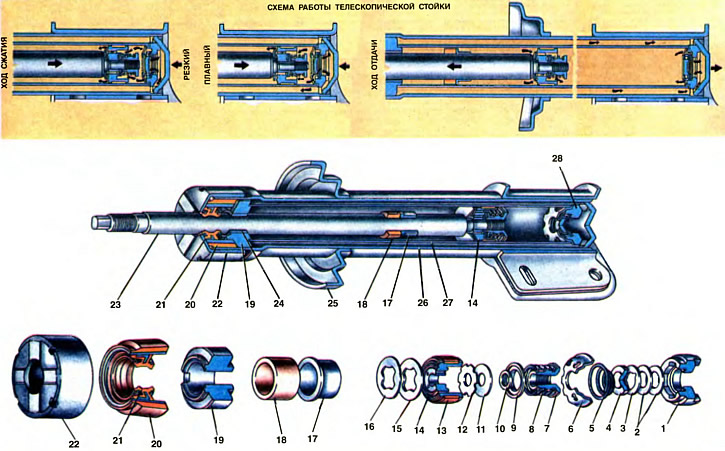
1. Compression valve body. 2. Compression valve discs. 3. Throttle disc compression valve. 4. Compression valve plate. 5. Compression valve spring. 6. Clip of the compression valve. 7. Recoil valve nut. 8. Recoil valve spring. 9. Recoil valve plate. 10. Nut washer. 11. Recoil valve disc. 12. Throttle disk of the recoil valve. 13. Piston ring. 14. Piston. 15. Bypass valve plate. 16. Bypass valve spring. 17. Rebound buffer stop. 18. Buffer release. 19. Rod guide sleeve. 20. Stuffing box. 21. Stem seal. 22. Housing nut. 23. Stock. 24. Stem guide bushing. 25. Spring cup. 26. Rack housing. 27. Cylinder. 28. Compression valve.
The main unit of the front suspension is a hydraulic telescopic strut, which combines the functions of a guide device and a damping suspension element. The guiding device includes the body of the strut and the details of fastening the strut to the body and to the steering knuckle, the damping element is a shock absorber mounted in the strut.
The body 26 of the rack is made of a pipe with an outer diameter of 48 mm. It is also the oil reservoir of the shock absorber. In the lower part of the housing, a terminal bracket for connecting to the steering knuckle and a mounting bracket for the brake hose guide sleeve are welded, in the middle part there is a support cup 25 of the suspension spring. There are two holes in the cheeks of the terminal bracket for the bolts of the rack to the steering knuckle. The top hole is oval, through it passes an eccentric bolt to adjust the camber of the front wheels. From below, a bottom is welded into the body of the rack, to which the compression valve 28 is pressed by the cylinder 27. Three flat discs 2 and 3 of the compression valve are pressed to the nest of its body by a spring 5. The upper disk 3 is throttle, it has three notches in the central hole. Through them, the fluid is throttled when the rod moves at low speed. In the two lower discs, 2 notches are missing. A clip 6 with holes for the passage of fluid is mounted on top of the compression valve body.
Cylinder 27 is made of a pipe with a diameter of 30 mm. A compression valve 28 is pressed into the cylinder from below, a clip 19 of the rod guide sleeve is pressed into the cylinder from above. A rod 23 is located in the cylinder, on which a piston 14 with valves and a guide stop 17 of the rebound buffer are mounted. The rubber buffer 18 of the recoil stroke rests on this stop, which, at the maximum recoil stroke, abuts against the holder of the rod guide sleeve.
The piston 14 is ceramic-metal. It is sealed in the cylinder with a fluoroplastic ring 13. The piston has eight vertical channels located along two radii, four in each. The channels of each radius are interconnected by an annular groove, each of which is closed by valves. The channels located on a smaller radius are blocked by disks 11 and 12 of the recoil valve, which are pressed against the groove seat by the spring 8 through the support plate 9. The recoil valve parts are attached to the stem with a nut 7, which is controlled by punching the end of the stem. Throttle disk 12 of the recoil valve has six cutouts along the outer diameter. The piston channels located along a larger radius are blocked by the bypass valve plate 15, which is pressed against the seat by a Belleville conical spring 18.
The movement of the rod in the cylinder is guided by bushing 24, which is pressed into cage 19. To reduce the wear of rubbing parts, a fluoroplastic insert is mounted in the guide bushing. There are two flats on the sides of the guide sleeve holder, and two grooves on the upper end. Through them, the cavity above the cage communicates with the cavity of the rack housing, so that when it comes into contact with air, the liquid does not foam and the liquid pressure is not created on the stem gland.
The stuffing box 21 of the rod is reinforced with a metal frame, as a result of which the necessary rigidity is achieved. The frame with the stuffing box is pressed into the body 20. Inside the stuffing box there are two working edges adjacent to the rod surface. The pressing of the edges is provided by springs embedded in the annular grooves of the stuffing box. The stuffing box frame is vulcanized to the outer rubber bushing, due to which the gap between the stuffing box and the rack body is sealed.
All parts located in the rack body are pressed with a nut 22 screwed onto the rack body 28. This nut is the stop for the compression stroke buffer.
Buffer 30 is fastened on top of the stem with a nut (see ch. 23) compression stroke with casing, upper support cup 28 springs, plain bearing (pos 28 and 29) and top support (pos 22, 23, 24, 25).
The buffer 30 of the compression stroke is made of fine-meshed polyurethane foam. From below, the edges of the polyethylene protective casing 31 enter the annular groove of the buffer. It protects the upper part of the rod from contamination and mechanical damage. The upper support cup 28 of the suspension spring rests on the compression stroke buffer, in the hole of which a plastic bushing 29 of the bearing is installed. Teflon fabric is fixed on the end face of the bushing. The thrust washer 28 of the bearing rests on the surface of the fabric. The end surfaces of the bushing and the washer form a plain bearing that operates when the front wheels are turned. Teflon fabric reduces friction forces and increases the durability of the bearing. The working surface of the bearing is sealed with a rubber ring 27, sandwiched between the thrust washer of the bearing and the support cup of the suspension spring. It prevents the penetration of dirt on the working surface of the bearing.
The upper support consists of a support body 22, to which rubber 23 is vulcanized, and two clips: 24 and 25. The rubber part of the support is clamped between the lower and upper clips. Two bolts are welded to the support body for fastening the telescopic strut to the front end strut.
Operation of the telescopic pole
The principle of operation of the telescopic strut, as well as the rear suspension shock absorber, is based on creating increased resistance to body swaying due to the forced flow of fluid through small flow sections in the valves. This resistance is transmitted through the strut body and the rod to the body.
Compression stroke
In this course, when the wheels of the car go up, i.e. the telescopic rack is compressed, the piston 14 goes down and displaces liquid from the lower part of the cylinder, part of which, overcoming the resistance of the spring 16 of the bypass valve 15, flows from the under-piston space to the over-piston space. All the liquid displaced cannot pass in this way, since the retractable rod 23 occupies part of the volume released by the piston, therefore the other part of the liquid, bending the inner edges of the disks 2 of the compression valve, flows from the cylinder into the rack housing. The compression stroke is limited by the buffer stop 30 (see ch. 23) into the rack housing nut (at the shock absorber of the rear suspension in the cover of the shock absorber housing).
With a smooth stroke of the stem, the force from the fluid pressure will be insufficient to press the inner edges of the compression valve discs, and the fluid will pass into the strut body through three cutouts of the throttle disc 3.
Recoil stroke
In this course, the wheels of the car, under the action of the elastic elements of the suspension, go down and the rack is stretched, i.e., the piston goes up. In this case, liquid pressure is created above the piston 14, and a vacuum is created below the piston. The liquid from the over-piston space, overcoming the resistance of the spring 8, bends the outer edges of the recoil valve disks 11 and flows into the lower part of the cylinder. In addition, due to rarefaction, part of the liquid from the housing, bending the outer edges of the compression valve disks from the valve body, flows into the lower part of the cylinder.
At a low piston speed, when the fluid pressure is insufficient to press the recoil valve discs, the fluid will be throttled through the side cutouts of the throttle disc 12, creating resistance to the recoil stroke. The limitation of the recoil stroke is provided by the stop of the buffer 18, which, at the maximum rebound stroke, abuts against the holder 19 of the rod guide bushing.