




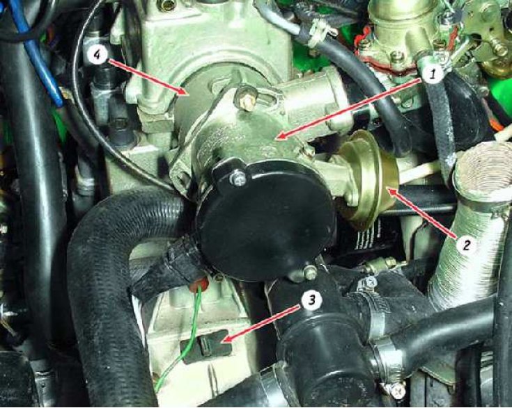
Location of spark timing sensor: 1 – spark timing sensor; 2 – vacuum corrector; 3 – clutch housing hatch plug; 4 – auxiliary engine drive housing
You will need:
- key "10"
- stroboscope (device for checking and setting the ignition timing of carburetor engines)
Before you start working remove the air filter (see subsection 3.9.).
The ignition advance angle is checked and set at engine idle (at a crankshaft speed of 820–900 min⁻¹). The angle for the VAZ-1111 should be within (1±1)° before TDC, for the VAZ-11113 – (4±1)° before TDC.
If the ignition timing is set incorrectly, the engine overheats, does not develop full power, and detonation occurs.
Marks for checking the ignition timing
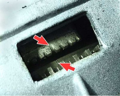
Check the ignition timing using the mark on the flywheel and the scale of the rear crankshaft oil seal holder (the rubber plug has been removed). When the mark on the flywheel is aligned with the middle division (notch) on the scale, the piston of the first cylinder is set at TDC. One division on the scale corresponds to 2° of crankshaft rotation.
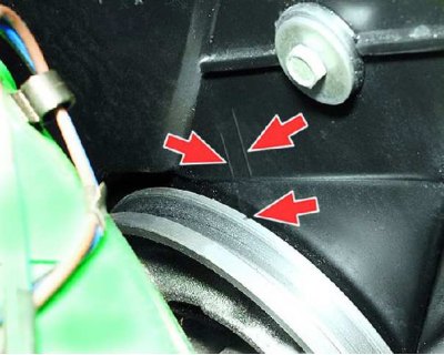
The ignition timing can also be checked and set using the marks on the generator drive pulley and the front cover of the camshaft drive belt. The long mark corresponds to the first cylinder being set to TDC, the short mark corresponds to the ignition timing being advanced by 5° of crankshaft rotation. The ignition timing is set using these marks on the stand.
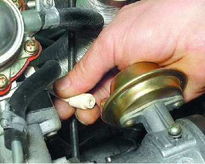
1. Disconnect the vacuum hose from the vacuum corrector.
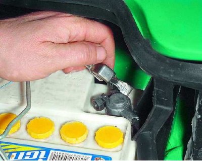
2. To check the ignition timing, connect the "+" clamp of the stroboscope to the "+" terminal of the battery, and...
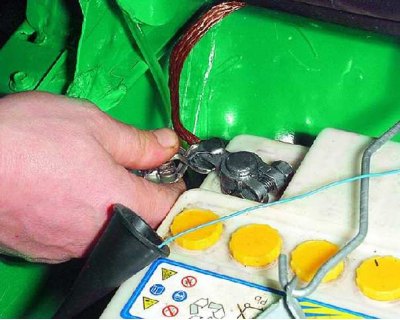
3....the stroboscope ground clamp is connected to the "–" terminal of the battery.
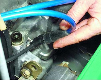
4. Remove the high-tension wire tip from the spark plug of the first cylinder and connect it to the timing light sensor in accordance with the instructions supplied with the timing light.
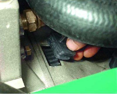
5. Remove the rubber plug from the clutch housing hatch.
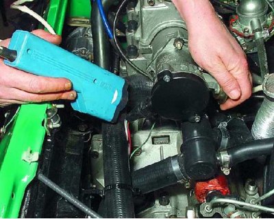
6. Start the engine and direct the flashing beam of the strobe light into the clutch housing hatch.
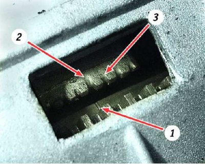
7. When the ignition timing is set correctly, mark 1 on the flywheel should be between the middle division 2 and the previous division 3 of the scale. Otherwise, it is necessary to adjust the ignition timing.
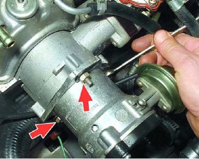
8. To set the ignition timing, loosen the three spark timing sensor mounting nuts.
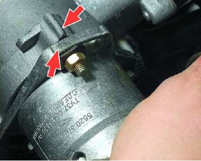
9. To increase the ignition advance angle, turn the sensor housing clockwise (the "-" mark on the sensor housing flange toward the protrusion on the auxiliary unit housing). In this case, one division on the flange corresponds to 8° of crankshaft rotation.
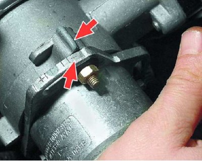
10. To decrease the ignition advance angle, turn the sensor housing counterclockwise (the "-" mark on the sensor housing flange to the protrusion on the auxiliary unit housing). Tighten the sensor mounting nuts, check and, if necessary, repeat the ignition timing setting. Connect the hose to the vacuum corrector.