
Disassembly and assembly
Disconnect tube 5 (see fig. 144) and remove dust caps 2 from the cylinders. Then, by forcing a jet of compressed air through the brake fluid inlet, the pistons 1 are pushed out of the cylinders on the caliper 4 and the sealing rings 3 are removed from the cylinders.
With prolonged use of the car, corrosion of the working cylinders occurs. In this case, as well as in case of wear or damage to the working surfaces of the cylinder or piston, the cylinder is replaced as an assembly. To do this, after performing the above operations, the caliper is clamped in a vice, the latches are drowned and the cylinder is knocked out of the caliper grooves with a rubber hammer. After that, a new cylinder is installed in the grooves.
Assemble the brake mechanism in reverse order. In this case, the sealing rings, pistons, cylinder mirror are lubricated with brake fluid.
Checking details
Carefully check all parts by washing them first with warm water and detergent and drying them with a jet of compressed air. If signs of wear or seizing are found on the piston or cylinder mirror, the cylinder is replaced complete with pistons. Whenever the piston is removed from the cylinder, it is recommended to replace the O-ring in the cylinder groove and the dust cap.
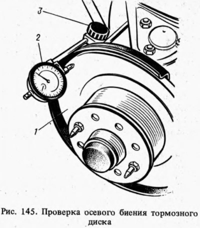
Checking brake disc runout
Axial runout of the brake disc 1 (pic. 145) check without removing it from the car. The largest allowable runout on the indicator 2 - 0.15 mm (the indicator is installed using a magnetic stand 3). If the runout is greater, the disc is machined using mandrel 67.7141.9500. Then it is ground, but the final thickness of the disk should not be less than 9.5 mm. In case of damage or very deep risks, as well as wear exceeding 0.5 on each side, replace the disc with a new one. In this case, the brake disc needs to be changed only in conjunction with the front wheel bearing hub, since its final processing is carried out assembled with the hub. Removal and installation of the hub with the brake disc are described in Sec. "Front suspension, wheels, tires".
Replacement of brake pads
The pads are replaced with new ones if the thickness of the pads has decreased to 1.5 mm. To replace the pads, cotter pins 14 are removed (see fig. 143) and fingers 8 with springs. Then the pads 16 and springs 15 are removed. Carefully, so as not to damage the dust caps and prevent the liquid from splashing out of the hydraulic drive reservoir, the pistons are sunk into the cylinders. New pads are installed, then fingers, springs and cotter pins, having previously applied a thin layer of some kind of grease to the surface of the fingers.