
Technical specifications
Wheels are disk, stamped; fixing the wheels with four bolts; the number of wheels is five, of which one is spare, placed in the trunk. The front wheels are interchangeable with the rear.

Open large image in new tab »
1. Disc wheel. 2. Guide pin. 3. Bolt. 4. Washer with a mustache. 5. Protective cap. 6. Nut. 7. Decorative cap. 8. Tapered roller bearing. 9. Front wheel hub. 10. Steering knuckle. 11. Clamping ring. 12. Tapered roller bearing. 13. Self-clamping gland. 14. Front brake disc. 15. Balance weight with spring. 16. Wheel rim. 17. A package of shims. 18. Hairpin of fastening of an axis of the bottom lever.
Front wheels
The hub 9 of the front wheel, made of cast iron, is mounted on the pivot 10 of the steering knuckle on tapered roller bearings 12 and 8. On the side of the steering knuckle, the bearing is protected from dirt and moisture by a self-clamping rubber seal 13. From lateral movements, the hub with bearings is fixed on the axle with a nut 6 (with right-hand thread on the left trunnion and left-hand thread on the right trunnion). Between the inner race of the outer roller bearing and the nut, there is a steel washer 4 with a mustache that keeps the washer from turning when the nut is tightened. Tightening the nut adjusts the axial clearance in tapered roller bearings, which should be equal to 0.02-0.08 mm. The maximum clearance allowed during the operation of the vehicle is not more than 0.15 mm.
The maximum tightening torque of the nut is 0.7 kgf·m, followed by loosening it by an angle of 20-25° (to ensure the necessary clearance in the bearings).
After adjusting the axial clearance in the bearings, the nut is locked with special pliers, pressing the holes on the nut collar into the upper and lower grooves on the threaded end of the trunnion.
From the ingress of dirt and moisture, the outer bearing and the cavity of the hub are protected by a steel cap 5 pressed into the bore of the hub.
Wheel bearing lubrication is permanent. For lubrication, LITOL-24 is used according to TU 38-1-01-139-71, which is laid in the hub cavity (40 g) and under the cap (25 g).
The brake disc 14 and its clamping ring 11 are attached to the mating flange of the hub with two steel guide pins 2.
Wheel disc 1 is centered on the hub by guide pins 2 and then fastened with four bolts 3. Hexagonal bolt heads 3 have conical seat belts designed for a tight fit of the fixed disc. The final tightening torque of the fastening bolts is 7 kgf·m.
The rear wheel disc is centered by two guide pins screwed into the axle shaft flange. The guide pins at the same time with their hexagonal heads fasten the brake drum, seated on the shoulder of the axle shaft flange.
The rear wheel disc is attached to the axle flange with the same bolts as the front wheel disc; the mating plane of the disc is pressed against the brake drum.
The wheel disk is stamped from a hot-rolled sheet of low-carbon steel with a thickness of 3.2–3.5 mm. On the disk, on the middle protruding part, there are three toes for installing and fixing the decorative cap 7 of the wheel. Eight evenly spaced ventilation windows are stamped along the circumference of the disk, at the section of transition to the collar.
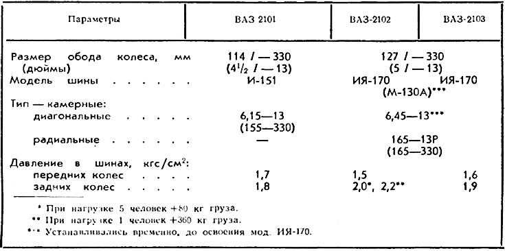
A wheel rim 16 is welded to the shoulder of the disk by spot welding. The wheel rim is made from cold rolled mild steel strip 2.5 mm thick. Deep rim profile with asymmetrical tire recess. Rim shelves for landing tires are tapered with an inclination angle of 5±1°. The largest diameter of the cone of the shelves is 329.4±0.4 mm, which approximately corresponds to the landing diameter of the tires.
At the bottom of the rim recess, its dimension in inches is applied (for example, 4½ - 13, where 4½ is the width of the rim for the tire, 13 is the diameter of the tire in inches), month (figures) and year of manufacture of the wheel.
Two types of tires are used on VAZ vehicles: diagonal and radial. In diagonal tires, the nylon cords are located in the tire carcass at an angle of approximately 52°to a plane drawn through the wheel axle. Such an arrangement of the cord gives good lateral rigidity of the tire, improves the stability and controllability of the car. Diagonal tires are used on VAZ-2101 cars.
However, the requirements for tires on VAZ-2102 and VAZ-2103 vehicles are more stringent, since the VAZ-2102 model is also used to transport goods, and the VAZ-2103 has higher speed performance. Therefore, they use radial tires.
The design feature of these tires is that the cords in the carcass layers are located radially along the tire profile in the direction from one side to another.
The radial arrangement of the nylon cord in the carcass increases the load capacity of the tire, reduces the radial stiffness and rolling resistance coefficient.
The tire tread has a complex pattern and provides good grip on paved roads. The depth of the tread pattern slots is approximately 9 mm. Longitudinal slots form three central treadmills. At the bottom of the slots in the tread pattern, there are six diametrically located protrusions 1.6 mm high and about 12.5 mm long along the top. These protrusions are called wear indicators, i.e. if the tread pattern wears out to the height of the indicators, then the tire must be replaced, since driving on a worn tire is unsafe.
The assembled wheel must be balanced on a special stand. Proper static and dynamic wheel balancing (complete with tires) is of great importance in eliminating wheel runout, which affects vehicle handling and tire wear uniformity.
The uneven distribution of mass relative to the axis of rotation of the wheel is balanced by installing balancing weights 15, made of antimony lead, weighing 20, 40, 60 or 80 g, on the side of the wheel rim. mounted on the outer and the other on the inner sides of the rim.
The weights are held on the side of the rim by springs.
Wheel alignment
When the car is moving, forces act on the steered wheels, deviating them from a given position. To stabilize the movement of the car, the front wheels have camber and convergence, and the axis of rotation of the wheels has longitudinal and transverse slopes.
The transverse slope, and with it the camber, causes the front end to rise when turning and reduces the turning arm, reduces the effect of reverse impacts on the steering wheel and contributes to the self-alignment of the wheels when the car goes straight.
Longitudinal tilt stabilizes the direction of the wheels when driving and increases the stability of the car when cornering.
Toe-in is used to compensate for elastic deformations of suspension parts and compensates for the undesirable effect of camber.
Properly adjusted wheel alignment ensures good handling and driving stability, as well as minimal tire wear. Violation of the angles of convergence and camber, especially, can cause intensive tire wear.
For a run-in car, the wheel alignment angles must be equal:
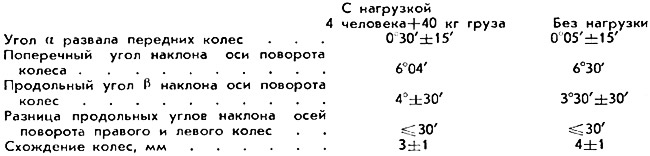
The collapse of the front wheels in elementary conditions can be measured by the difference in the distances C and D between the square and the same point on the wheel rim. Size D should be 1-5 mm larger than size B.
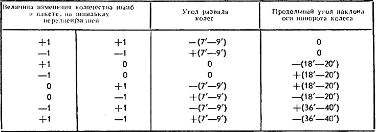
The camber angle of the front wheels and the angle of longitudinal inclination of the axis of rotation are regulated by changing the number of shims 17 mounted on two studs 18 of the axle between the axle of the lower arm of the front suspension and the cross member.
Below are the values of the change in the camber angles and the longitudinal inclination of the axis of rotation when changing the number of washers in the packages.
Wheel toe-in is measured by the difference in distances between the same points on the wheel rims in positions A and B in a horizontal plane passing through the wheel axle, front and rear, and is regulated by changing the length of the extreme steering rods.
Note: 1. The angles of installation and convergence of the wheels are regulated under certain conditions, i.e. the air pressure in the tires must comply with the norm, the value of the radial and axial runout of the tires is not more than 3 mm. axial clearance in the front wheel hub bearings is not more than 0.1 mm, shock absorbers must work flawlessly (do not jam), lack of play in the upper ball joints, the clearance in the steering on the free play of the steering wheel should be normal.
Note: 2. The transverse angle of inclination of the axis of rotation of the wheel is set constructively and is not subject to regulation.