




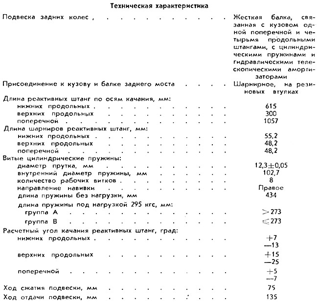
The rear wheel suspension has devices that are specific to each suspension, i.e. guiding, elastic and damping.
Guide device. The rear axle beam is attached to the car body using reaction rods: two upper longitudinal, two lower longitudinal and one transverse.
The longitudinal rods serve to transmit pushing and braking forces from the drive wheels through the beam to the body, the transverse rod prevents the body from lateral movements.
All rod fastenings, both on the rear axle beam and to the body, are articulated, made on rubber bushings, and do not require additional maintenance or lubrication during operation.
Open large image in new tab »
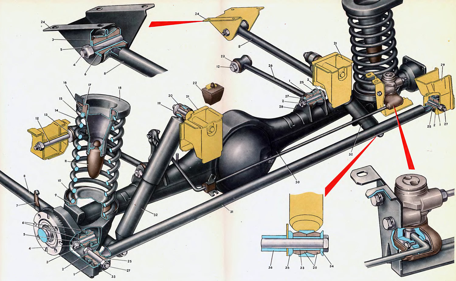
1. Expansion sleeve. 2. Pressure washer. 3. Conical rubber bushing of the lower rod. 4. Fastening bolt of the lower rod head. 5. Expansion sleeve. 6. Pressure washer. 7. Parking brake cable fastening bracket. 8. Lower longitudinal rod. 9. Insulating plastic gasket. 10. Cup of the lower spring support. 11. Main compression buffer. 12. Fastening bolt of the upper rod head. 13. Body floor side member. 14. Spring. 15. Support of the compression buffer. 16. Support cup. 17. Rubber insulating gasket 18. Upper spring support. 19. Washer. 20. Rubber bushing. 21. Bracket of the rear floor cross member of the body. 22. Additional compression buffer. 23. Front head of the upper rod. 24. Front head of the lower rod mounting bracket. 25. Conical rubber bushing of the upper and cross rods. 26. Upper longitudinal rod. 27. Bolt for mounting the heads of the upper and cross rods. 28. Mounting bracket for the rear head of the upper rod. 29. Mounting bracket for the right head of the cross rod. 30. Rear axle beam. 31. Cross rod. 32. Shock absorber. 33. Mounting bracket for the left head of the cross rod. 34. Pressure washer. 35. Washer. 36. Spacer sleeve.
The design of the cross 31 and lower rods 8 is the same and is a steel pipe ∅ 30X26 mm, to the flattened ends of which conical heads are welded. Rubber bushings 3 and 25, made in the form of truncated cones, are pressed into these heads. This design of the bushings creates their good fixation in the rod head. From the outside, the rubber bushings are pressed by steel washers 2 and 6. The washers are fixed by flaring the flanges of the steel spacer bushings 5 and 1, inserted into the holes of the rubber in the hum.
The heads with pressed-in bushings of the lower longitudinal rods are longer than the heads of the transverse rod, since the lower rods are the main ones and bear a greater load.
The upper longitudinal rods 26 are shorter than the lower ones and are steel rods ∅ 16 mm with conical bushings welded to the ends, similar in design to the heads of the other rods.
Bracket 7 for fastening the parking brake cable is welded to the outer side of the lower longitudinal rods using relief welding. Bracket 7 limits the lateral displacement of the cable.
All reaction rods are coated with black paint for anti-corrosion protection and decorative appearance.
The front heads of the lower longitudinal rods are attached to the brackets 24 of the body using bolts 4. The rear heads of the rods are reinforced with bolts 4 in brackets welded from below to the rear axle beam.
The front heads of the upper longitudinal rods are secured with 12 bolts with self-locking nuts (with nylon inserts) to the inner wall of the side members 13 of the body floor, and the rear heads of the rods - to the brackets 28, welded from above to the beam 30 of the rear axle, with bolts 27 with nuts and spring washers.
The left head of the crossbar is attached to bracket 33, welded to the flange and casing of the rear axle beam, and the right head is attached to bracket 29 with bolts, nuts and spring washers.
The final tightening of the fastening nuts with a torque of 8 kgf·m for all reaction rods is carried out on a vehicle with a nominal load of 320 kg (4 people plus 40 kg of cargo in the trunk). This is done to ensure optimal conditions for the operation of the articulated joints. Tightening the fasteners ensures a tight fit of the pressure washers 6, 2 and the spacer bushings 5 and 1 to the bracket cheeks and does not allow these parts to rotate when the body or suspension oscillates relative to the fastening bolts.
The swinging of the rods during vibrations occurs only due to the elastic deformation of the rubber bushings without their slipping.
Elastic device. The main element of the elastic device is a coiled cylindrical spring 14. The spring is made by winding in a heated state from a ground rod of chromium-silicon steel, hardened with high tempering (improvement) and subjected to shot blasting to increase fatigue strength. After processing, a protective polyamide coating is applied to the rear spring, the front spring is painted.
The springs are sorted by length into two groups under a static load of 295 kg. On the outer side of the springs, the group marking is applied with paint similar to the groups of front suspension springs, i.e. group A - yellow stripe, group B - green stripe.
The spring installed on the suspension is pre-compressed by a force of up to 65-70 kgf. The upper end of the spring rests against support 18 welded to the rear wheel arch. A rubber insulating gasket 17 and a stamped steel cup 16 are installed between support 18 and the spring.
The lower end of the spring rests through an insulating plastic gasket 9 in a cup 10 welded to the beam 30 of the rear axle.
The rear suspension travel is limited by two main 11 and one additional 22 compression buffers. The buffers are made of rubber that works well under compression and are additional elastic elements that increase the rigidity of the suspension at the end of the compression stroke.
The main buffers 11 are installed inside the springs and are secured with a mushroom-shaped nipple in the holes of the upper supports 15. At the end of the compression stroke, the buffer rests against the plate-shaped bottom of the lower cup 10.
Additional buffer 22 is mounted on a bracket secured with bolts to the bottom of the body (this bracket also serves as a seat belt mount), and at the end of the suspension compression stroke it rests against a special platform on the rear axle gearbox housing.
Damping device. Just like on the front suspension, two hydraulic shock absorbers are used as the main element of the damping device.
Unlike the front shock absorbers, the rear shock absorbers have two heads for connection to the mounting points. All shock absorber mounts are hinged, on rubber bushings, which operate due to the elastic deformation of the rubber when the suspension and body oscillate. During operation, these hinged joints do not require lubrication. Calculated shock absorber deflection angle (when fluctuating) — with a compression stroke of 9° and a recoil stroke of 10°.
The shock absorber is secured with its upper head on a pin welded to bracket 21 of the crossmember of the rear floor of the body. When securing the shock absorber, two rubber bushings 20 are inserted into the conical opening of the head, then pressed by washer 19 and a self-locking nut. The shock absorber is secured with its lower head to the ears of the bracket for fastening the lower longitudinal rods using a bolt with a self-locking nut. When fastening, two rubber bushings 20 are also inserted into the conical opening of the head, and a steel spacer bushing 33 is inserted into the openings of the bushings. The rubber bushings are pressed on both sides by steel washers 34 and 35. To protect the bracket ears from deformation when tightening the nut, a distance steel bushing 36 is inserted between them. The final tightening of the upper and lower fastening nuts with a torque of 6 kgf·m is performed with a vehicle load of 320 kg (4 people + 40 kg of cargo in the trunk).
The bushings of the articulated joints and the insulating pads of the springs are also elements of the damping device, absorbing micro-vibrations and reducing the vibration of the body that occurs when the car is moving.
Original source is on the resource VazBook.ru