




Open large image in new tab »
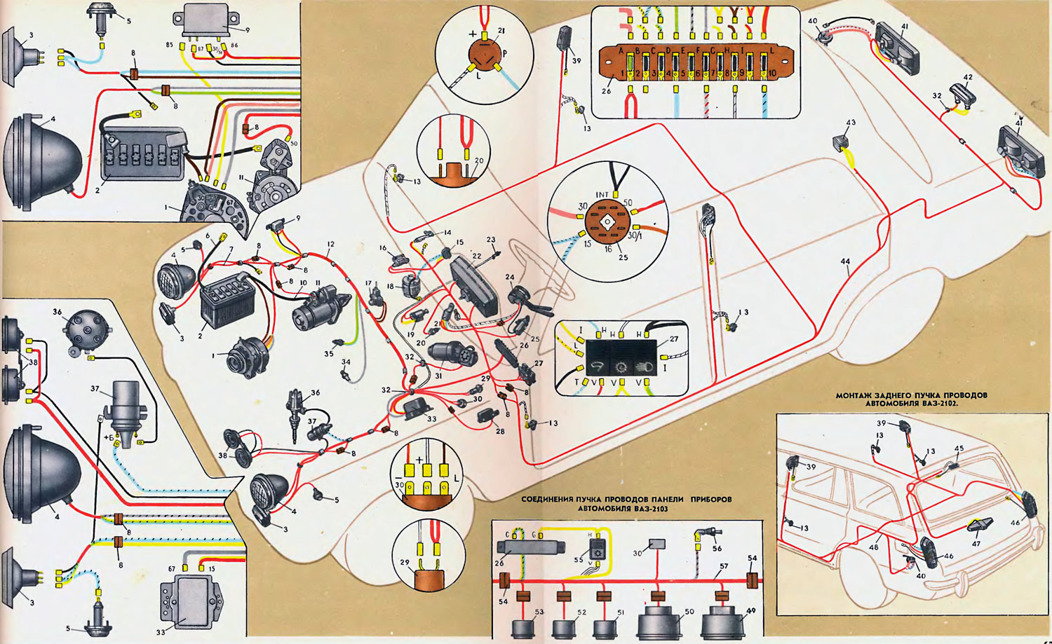
1. Generator. 2. Battery. 3. Side lights. 4. Headlights. 5. Side direction indicators. 6. Battery ground wire. 7. Side light wire harness. 8. Plug and socket. 9. Battery charge indicator lamp relay. 10. Battery wire harness. 11. Starter. 12. Front wire harness. 13. Door pillar light switches. 14. Glove compartment light. 15. Heater motor switch. 16. Heater motor additional resistor. 17. Underhood light. 18. Heater motor. 19. Cigarette lighter. 20. Brake light switch. 21. Direction indicator flasher relay. 22. Instrument cluster. 23. Parking brake indicator lamp switch. 24. Direction indicator and headlight switch. 25. Ignition switch. 26. Fuse box. 27. Switch block. 28. Windscreen wiper relay. 29. Portable lamp socket. 30. Parking brake indicator lamp flasher relay. 31. Windscreen wiper motor. 32. Wire seal. 33. Voltage regulator. 34. Oil pressure indicator lamp sensor. 35. Coolant temperature gauge sensor. 36. Ignition distributor. 37. Ignition coil. 38. Horns. 39. Interior lights. 40. Fuel level gauge and fuel reserve indicator lamp sensor. 41. Tail lights. 42. License plate light. 43. Trunk light. 44. Rear wiring harness. 45. Rear interior light (VAZ-2102). 46. Taillights of the VAZ-2102 car 47. License plate light of the VAZ-2102 car. 48. Rear wiring harness of the VAZ-2102 car. 49. Speedometer of the VAZ-2103 car. 50. Tachometer of the VAZ-2103 car. 51. Oil pressure gauge of the VAZ-2103 car. 52. Coolant temperature gauge of the VAZ-2103 car. 53. Fuel level gauge of the VAZ-2103 car. 54. Plug-and-socket connectors for connecting the instrument panel wire harness to the front wire harness of the VAZ-2103 car. 55. Instrument lighting switch of the VAZ-2103 car. 56. Switch for the control lamp of the air damper of the carburetor of the VAZ-2103 car. 57. Wiring harness of the instrument panel of the VAZ-2103 car.
To connect the electrical equipment units into a common circuit on Zhiguli cars, low-voltage wires of the PVA type are used, which have a conductive core and polyvinyl chloride insulation that is resistant to oil, gasoline and maintains functionality in the temperature range from -40 to +105°C. The wire insulation is painted in one of the following ten colors: white, blue, green, orange, red, brown, pink, gray and black. In addition, ring stripes of white, blue, red or black colors can be applied to the surface of the insulation.
Since different wires carry different strengths of electric current, the cross-section of the wire cores is also different. The greater the strength of the electric current, the larger the cross-section of the wire core.
The engine is connected to the ground by a wire with a cross-section of 16 mm². The tip of one end of the wire is bolted to the clutch housing, and the other is welded to the body.
To facilitate installation, all wires are combined into bundles. The wires in the bundles are wrapped with adhesive tape or enclosed in plastic tubes. The bundles of wires are connected to each other using plug connectors, the blocks of which are made of polyamide plastic. The holes in the body through which the wires pass are covered with rubber seals 32, etc., which protect the wires from damage on the edges of the holes and do not allow water and dirt to penetrate through the holes.
On the VAZ-2101 car there are only five bundles: front bundle 12, rear 44, right and left bundles 7 of headlights and side turn signals and bundle 10 of battery wires.
The front bundle 12 has three main branches. Two of them are in the engine compartment, and the third is in the passenger compartment under the instrument panel. From the engine compartment to the passenger compartment, the front bundle of wires passes through the seal 32. After exiting the seal, the bundle of wires branches. The right branch of the bundle is laid on the front shield and the right mudguard of the body, and the left one is on the left mudguard. On the front shield and mudguards, the wires are fastened with steel brackets welded to the body, and plastic clamps.
The front bundle 12 is connected to the sidelight wire bundles and to the headlight wires by two-plug connectors. The red wire going to the starter terminal "50" is connected to the wire bundle by a single-plug connector.
The end of wire 6, which connects the battery to ground, is secured with a bolt to the right mudguard; the bolt nut is welded to the mudguard. The ends of the ground wires from the 7 sidelights are also attached to the mudguards, with the end of the wire of the left sidelight being installed under the ignition coil mounting nut, and the right one is attached to the mudguard with a self-tapping screw.
To protect electrical connections from water and dirt, the rear of the sidelights is covered with rubber covers. Protective rubber caps cover the high-voltage wire tips, coolant temperature and oil pressure sensors, as well as the "+" terminal of the battery and the "30" terminal of the generator.
The front bundle is connected to the rear wire bundle by two plug connectors: a two-plug (for wires to the fuel level indicator sensor) and six-plug (for wires to lighting and light signaling devices).
(The text is taken from the online resource: «VazBook.ru»)
In the car's interior, the front bundle runs under the instrument panel and has small branches that go to the fuse box 26, the switch box 27, the instrument cluster 22, the ignition switch 25 and other devices. The tip of the three wires (two black and one black and white), coming from the bundle to the "ground", is secured to the bolt of the turn signal flasher relay.
The rear bundle runs back along the left side of the body floor and has branches to the interior lighting lamps 39 and to the trunk lighting lamp 43. The branch to the right lamp runs behind the rear crossbar of the body floor. The wires of the bundle are attached to the body floor with adhesive tape and plastic ties.
The ends of the wires (black) connecting the lamps to the ground are attached to the door pillars with self-tapping screws. The ends of the wire connecting the fuel gauge sensor to the ground are attached under the screws securing the sensor and the right rear light.
Features of wiring installation on the VAZ-2102 car. The wires of the front wiring bundle on the VAZ-2101 and 2102 cars are laid in the same way. There are features in the installation of the rear bundle, associated with a different shape of the rear part of the body.
Just like on the VAZ-2101, the rear bundle of wires first runs along the left side of the body floor and has a branch to the left ceiling light 39. Then behind the rear crossbar of the body floor it divides into two branches: one - to the right ceiling light and the right rear light 46, the other - to the left rear light and has a branch to the fuel gauge sensor. From the left rear light, the bundle goes up along the rear pillar of the body and near the left hinge of the rear door it divides into two branches: one - along the rear edge of the roof to the rear ceiling light 45 of the body lighting, the other - goes down the door to the light 47 of the license plate lighting.
The tip of the black wire connecting lamp 45 and the license plate light to ground is secured with a self-tapping screw to the rear edge of the roof at a distance of 260 mm from lamp 45. The tips of the black wires connecting the rear lights to ground are secured with self-tapping screws to the sides of the body at a distance of 200 mm from the lights.
Features of wiring installation on the VAZ-2103 car. On the VAZ-2103, the wire bundles are laid in the same way as on the VAZ-2101, but unlike the VAZ-2101, there is a sixth wire bundle 57, connecting the control devices with the front wire bundle through plug connectors 54. In addition, on the VAZ-2103, the brown wire from the "+" terminal of the battery does not go directly to the "30" terminal of the generator, but is connected to a four-plug connector block, which is fixed on the right mudguard. From the block, the wires go: one - brown to the "30" terminal of the generator, the other - brown to the high beam relay and pink to the "A" plug of the fuse box.
Connecting wires to new electrical equipment units (to the headlight relay, to the horn relay, to the fan motor and to other new units) can be seen further on those sheets where these nodes are described.