
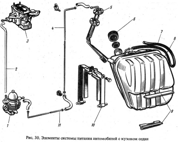
Fuel tank
Steel, stamped from leaded steel sheet. It is installed in the trunk on the right side on gaskets 9 and fastened with two clamps 10 tightened with a bolt. The filler neck is brought out under the hatch in the right rear wing and is closed with a blind screw plug 6. The tank is connected by an air tube 7 to the atmosphere. The fuel in the tube loop 7 reduces the evaporation of gasoline in the tank. Access to the drain plug of the tank is through a hole in the floor of the body. In the tank, combined are installed - in one assembly unit 5 a gas receiver and an indicator of the level and reserve of fuel.
The fuel tank on cars 2102 and 21021 is installed under the rear floor of the body.
Fuel pump
Diaphragm type, mechanically driven, mounted on the left side of the cylinder block and has manual pumping (pic. 31). Driven by a pusher from the eccentric of the oil pump drive shaft. The pump consists of a lower housing 13 with drive levers, an upper housing 3 with valves and nozzles, a diaphragm assembly and a cover 5. Spacers 14 and 15 are installed between the two upper working diaphragms for fuel supply and the lower safety diaphragm, which operates in contact with crankcase oil..Outer gasket 15 has a hole for fuel to escape to the outside in case of damage to the working diaphragms.
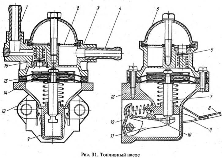
Textolite valves are installed in the upper body 3: inlet 6 and outlet 16. The valve seats are brass. A plastic mesh filter 2 is placed under the cover 5. In the lower housing 13, a lever 12 with a balancer 11 and a lever 8 for manual fuel pumping with a spring 9 are installed, acting on the balancer through the cam 10.
When the engine is running, the eccentric of the oil pump drive shaft acts through the pusher on the lever 12 and turns the balancer 11, which pulls the pump diaphragm with the rod 7. Under the action of rarefaction, fuel fills the working cavity through pipe 4 through valve 6. When the eccentric runs off the pusher, the lever 12, the balance bar and the stem, with diaphragms, are released. The diaphragms close the inlet valve and, through the outlet valve 16, supply fuel to the carburetor float chamber through pipe 1.
With a small fuel consumption, the stroke of the diaphragms will be incomplete, so the stroke of the lever 12 will be partially idle.
Air filter
Dry type, consists of body, cover and filter element (see fig. 26). The body has a branch pipe for intake of cold air in summer and a branch pipe for air intake heated from the exhaust manifold through a corrugated hose in winter. The dry filter element consists of a cardboard accordion sandwiched between the housing and the cover. For preliminary air purification, an element of synthetic wool is put on the cardboard filter. A collector with a branch pipe for suction of exhaust gases from the crankcase is welded to the body from the bottom side.