




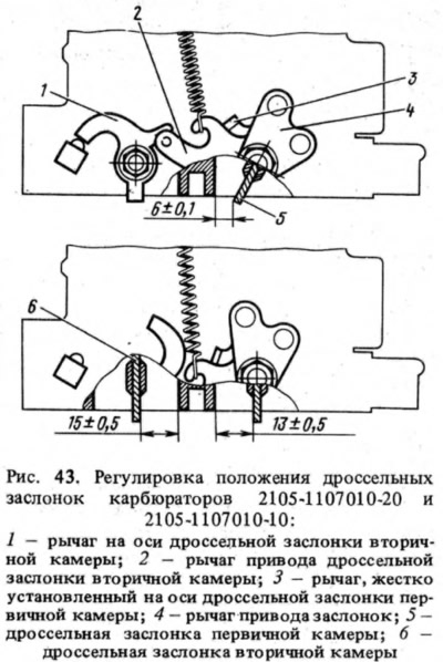
When adjusting the positions of the throttle valves on carburetors 2105-1107010-20 and 2105-1107010-10, check the full opening of the throttle valves when turning the drive levers to the stop, Maximum opening of the primary chamber throttle valve (13 mm ±0.5 mm) 3 (Fig. 43); the same for the secondary chamber throttle valve (15 mm ±0.5 mm) — by screwing or unscrewing the pneumatic actuator rod. Partial opening of the primary chamber throttle valve (6 mm ±0.1 mm), at which the upper antenna of lever 3 contacts lever 2, is regulated by bending the upper antenna of lever 3.
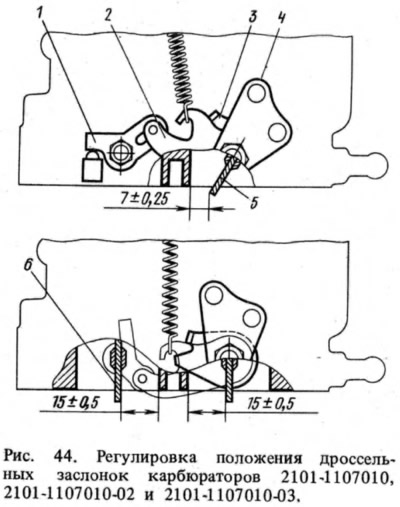
For carburetors 2101-1107010-03, 2101-1107010-02 and 2101-1107010, with lever 4 in position (Fig. 44), when the upper antenna of lever 3 touches lever 2, the primary chamber throttle valve should be slightly open by (7±0.25) mm. Adjusted by bending the upper antenna of lever 3. Both throttle valves should be fully open when lever 4 is turned to the extreme position until the antenna of lever 3 stops in a special lug on the throttle valve body. Adjusted by bending the lower antenna of lever 3.
When adjusting the starting device, turn lever 1 (see fig. 34) counterclockwise until it stops. In this case, the air damper should be completely closed. In this position of the lever, the end of the rod 3 should be at the end of the groove of the rod 4, without moving the rod. With the air damper completely closed, the throttle valve 6 of the primary chamber should be slightly open for carburetors 2105-1107010-20 and 2105-1107010-10 by 0.7-0.8 mm (gap C). It is adjusted by bending the rod 7. Gap C for carburetors 2101-1107010 should be 0.75-0.85 mm, for carburetors 2101-1107010-03 and 2101-1107010-02 - 0.80-0.85 mm. A fully closed air damper should open (gap B) when rod 4 is moved manually to the stop by (7±0.25) mm for carburetors 2101-1107010-03, (8±0.5) mm for carburetors 2101-1107010-02 and 2101-1107010, (5±0.5) mm for carburetors 2105-1107010-20 and 2105-1107010-10. This value is adjusted by screw 5.
The opening of the float chamber unbalance valve is checked with the throttle valves fully closed.
The accelerator pump feed is checked by 10 full turns of lever 5 (see fig. 32) throttle valve. Fuel from the sprayer is collected in a measuring cup. Its volume should be 5.25-8.75 cm³. Before starting the test, it is necessary to make 10 test turns (strokes) to fill the channels of the accelerator pump.
The tightness of the needle valve is checked on a stand that supplies fuel to the carburetor under a pressure of 3 m of water column. After the level is set in the stand's control tube, its fall is not allowed for 10-15 seconds. A decrease in the level in the tube indicates a fuel leak through the needle valve.
[The article is taken from the website: VAZBOOK]