
Pressure Regulator Drive Parts
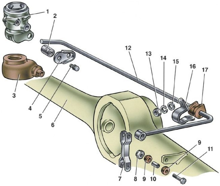
1 - pressure regulator; 2 – axis of the regulator drive lever; 3 - dirt cap; 4 - locking plate; 5 - bolt with spring washer; 6 - rear axle; 7 – thrust connecting the pressure regulator drive lever with the bracket of the rear axle beam; 8 - bolt nut; 9 - plastic sleeve; 10 - spacer sleeve; 11 – a bolt of fastening of draft; 12 - pressure regulator drive lever; 13 – a nut for fastening of a bracket to a body; 14 - spring washer; 15 - flat washer; 16 - bracket for fastening the pressure regulator drive lever; 17 - rubber bushing
1. Disconnect lever 12 (see fig. Pressure Regulator Drive Parts) from the rod 7, and then the bracket 16 from the body and the bracket for fastening the pipelines going to the pressure regulator.
2. Disconnect the muffler suspension parts from the body and take the pipeline with the mufflers to the side.
3. Having unscrewed the bolts securing the regulator to the bracket and the bracket to the body, remove the regulator bracket, and then, lowering the regulator down, disconnect the pipelines from it.
4. Remove the regulator and disconnect the drive lever from it. Plug the inlets and outlets of the pressure regulator and piping.
5. Install the pressure regulator in the reverse order of removal when the rear axle of the car is suspended.
6. Before tightening the regulator mounting bolts, install tool 67.7820.9518 on the end of the regulator drive lever (see fig. Installing tool 67.7820.9518 for adjusting the rear brake pressure regulator).
7. Direct the tool rod up until it stops in the body. This sets the distance of 140±5 mm between the end of the lever 4 (see fig. Installation diagram of the rear brake pressure regulator and its adjustment) and body spar.
8. Lift up the protective cap 3 (see fig. Pressure Regulator Drive Parts) and, turning the regulator on the fastening bolts, ensure that the end of the lever is in light contact with the regulator piston.
9. While holding the regulator in this position, tighten the bolts of its fastening to failure, then cover the axis 2 and the protruding part of the piston with a layer of grease DT-1. Reinstall the rubber cap 3, filling it with 5-6 g of the same lubricant.
10. Remove fixture 67.7820.9518 and connect the end of the lever with the rod 7, having previously lubricated with grease DT-1 the bushings of the swivel link with the lever.
11. Attach the pipes of the exhaust system to the body.
12. Then bleed the brakes to remove air from the rear brake actuator.