
- grease Fiol-1 is applied to splined joints;
- when connecting the parts, the marks applied to the detachable parts before disassembly are combined;
- after assembling the spline connection, pressing the stuffing box by 0.3-0.5 mm with an axial load, compress the clip on the groove of the fork; tighten the front propeller shaft yoke nut with a torque wrench (see annex 1) and minted.
When assembling the intermediate support, the bearing is pressed with a mandrel, the outer diameter of the punch of which is equal to the diameter of the installed bearing - 52 mm, and the support with the bearing on the shaft with a tubular mandrel of the same size.
The universal joint is assembled in the following order. After removing the old thickened grease, fill the cavities in the spikes of the cross and lubricate the inner surface of the bearing housings with Fiol-2U grease (0.4-0.6g per bearing). The spikes of the cross are not lubricated so that an air cushion does not form during assembly. Insert the spikes of the cross into the fork. Bearing housings with needles are put on the spikes of the cross and pressed into the fork holes with a force of 800 kgf. Install the retaining rings in the grooves of the fork in their original places according to the marks.
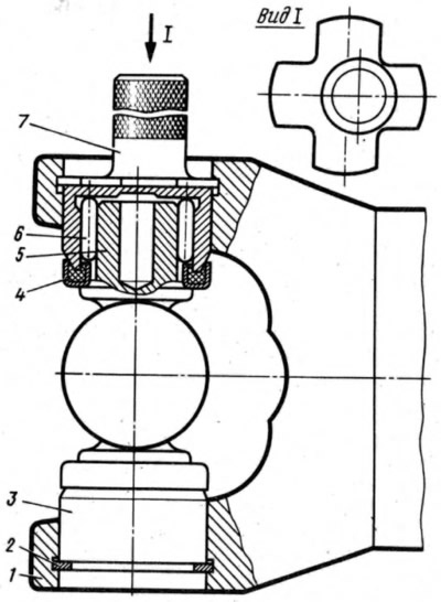
In case of replacement of parts of the universal joint, the retaining rings are selected by thickness with caliber 41.7834.4092, which has four petals of different thicknesses (1.53mm; 1.56mm; 1.59mm; 1.62 mm). To do this, install the retaining ring 2 (pic. 78) 1.56 mm thick. When pressing bearings 3, 6 into yoke 7, when crosspiece 5 with stuffing box 4 abuts against bearing housing (in this case there are no gaps), gauge 7 determine the distance between the bearing housing and the end face of the annular groove. Depending on the measured distance, taking into account the axial clearance of 0.01-0.04 mm, a second retaining ring of the appropriate thickness is inserted.
Having installed the retaining rings, they hit the turns with a hammer with a plastic striker. Under the action of the impact between the bearing and the retaining ring, gaps are selected and appear between the bearing housings and the ends of the cross spikes. After assembly, check the ease of turning the hinge forks.
Shaft balancing
If parts of the driveline were replaced during the repair, then its balancing is required. Dynamic balancing of cardan shafts in the assembled state is not carried out on a special bench.
At a speed of 5500 rpm, the largest permissible unbalance when checking the balance should not exceed (no text) achieved by welding metal plates 25 (see fig. 76).