
Removal and installation
Disconnect the pipelines from the master cylinder and the block with wires from the terminals of the brake fluid emergency level sensor. Close the openings at the pipelines and at the master cylinder to prevent leakage of fluid and the ingress of dirt into them. Remove the cylinder assembly with the reservoir by unscrewing the nuts securing it to the vacuum booster. Remove the emergency brake fluid level sensor and drain the brake fluid from the reservoir and cylinder. It is not recommended to remove the reservoir from the master cylinder unless it is necessary.
Installation of the master cylinder is carried out in the reverse order of removal. After installing the cylinder, the hydraulic brake drive is pumped to remove air.
Disassembly and assembly
If necessary, remove tank 13 from the master cylinder (see fig. 108), for which they pull it out with effort. Having unscrewed the locking screws 10, all parts are sequentially removed from the cylinder. The assembly of the cylinder is carried out in the reverse order of disassembly. In this case, all parts are lubricated with brake fluid. Gaskets under locking screws 10 are recommended to be replaced with new ones.
Checking parts before assembly
Rinse all parts with isopropyl alcohol, dry with compressed air or wipe with a clean cloth, avoiding contact with mineral oils, kerosene or diesel fuel, which can damage the seals. The time of flushing the O-rings in isopropyl alcohol should not exceed 20 s, after which they are blown with compressed air. The cylinder mirror and the working surface of the pistons must be completely clean, free of rust, scratches and other defects. At each disassembly of the cylinder, replace the sealing rings 2 and 5 (see fig. 108), even if they are in good condition. Check the elasticity of the spring 8 of the piston, the length of which should be: 36 mm under a load of 3.5-4.2 kgf; 21 mm under load 6.35-7.35 kgf; 57.5 mm free.
Master Cylinder Leak Test
The main cylinder is installed on the stand BS-134.000 and connected to the elements of the stand, as shown in fig. 115. Fill the tank 4 of the cylinder with brake fluid and, moving the pistons of the main cylinder 7 several times to the full length of their stroke, pump the system through the valves 3. Rotating the flywheel 5, slowly move the pistons of the main cylinder until the pressure controlled by the pressure gauges 2 will reach 125 kgf/cm2. In this position, fixed by pointer 5, the pusher of the master cylinder is blocked. The specified pressure must remain constant for at least 5 s. If fluid leaks or pressure changes during this time, replace the piston o-rings. To ensure the accuracy of pressure gauge readings 2, the stand is equipped with absorbing cylinders 1.
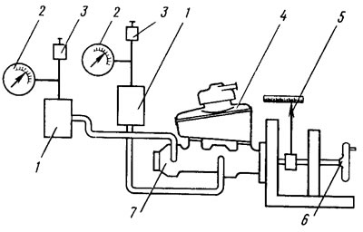
Pic. 115. Scheme for checking the tightness of the master cylinder