
Removal and installation
Raise the front of the car, put it on stands and remove the wheel. Unscrew the fitting of the pipeline and disconnect the flexible hose from the line; plug the hose and tube openings to prevent leakage of brake fluid. Remove the hose from the guide bracket. Having unscrewed the two bolts with which the shoe guide is attached to the steering knuckle, remove the guide assembly with the caliper and the working cylinder.
Installation of the brake mechanism is carried out in the reverse order. After installation, restore the level of brake fluid in the tank and pump the hydraulic drive to remove air.
Disassembly and assembly
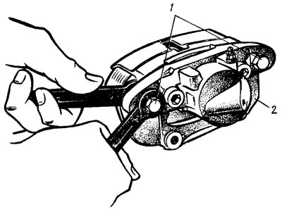
Pic. 119. Unscrewing the cylinder bolt
Disconnect hose from wheel cylinder 2 (pic. 119). Unlock and unscrew the bolts 1 for fastening the wheel cylinder to the guide pins, holding the guide pin by the edge with a wrench so as not to damage the protective cover. Remove guide 8 (pic. 120) block assembly with fingers. Remove the brake pads 9. It is not recommended to unscrew the bolts 14 connecting the caliper and cylinder, except when replacing the caliper or cylinder.
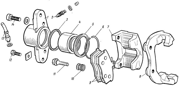
Pic. 120. Front wheel brake parts
Remove retaining ring 6 (see fig. 120) and protective cap 5 from the cylinder and piston. Gently, by forcing a stream of compressed air through the hole for the hose 13, push the piston 4 out of the cylinder 1. In order not to damage the piston on the surface of the caliper 7 when pushing out, a wooden lining is installed under the piston. The bleed valve 2 is unscrewed from the cylinder body and the working surface of the cylinder is carefully inspected. It must be free of scratches, damage and corrosion.
Assembly of the brake mechanism is carried out in the reverse order. In this case, the sealing ring 3 and cap 5 are recommended to be replaced with new ones. The cylinder mirror, piston and sealing ring are lubricated with brake fluid, and graphite grease is applied to the piston surface, the piston is installed in the cylinder and, without removing grease residues, protective cap 5 is put on so that its edges enter the grooves of the piston and cylinder, after which a locking cap is installed. ring 6. Guide pins 11 are lubricated with Uniol-1 grease. Bolts 12 for fastening the caliper and cylinder to the fingers are tightened with the torques indicated in appendix. 1, after which they will be countered. Before tightening the bolts, a sealant is applied to them so that the threaded part of the connection does not corrode. After assembling and installing the brake mechanism, the fluid level in the reservoir is restored and the hydraulic drive is pumped.
Checking the technical condition
Clean all parts and carefully check their condition for signs of wear, damage or corrosion. Particular attention is paid to the surface of the piston and cylinder. If they are worn, damaged or severely corroded, the cylinder and piston are replaced. Corrosion is removed from the cylinder body with a wire brush. Check guide pins 11 (see fig. 120) and their sealing boots 10. Make sure that the fingers are not corroded and damaged, that they do not stick in the holes of the guide. Fingers should move freely. In case of corrosion and damage, replace the fingers and protective covers with new ones. Check the condition of the brake disc. On its working surface, scuffing and deep scratches, as well as other damages that increase wear of the linings or reduce braking efficiency, are not allowed. Check the thickness of the disk, which must be at least 10.8 mm. If the thickness is less than specified, replace the disc. It is allowed to turn or grind the discs, but both sides must be machined to the same depth, and the thickness of the disc should not be less than 10.8 mm as a result. Brake pads are replaced with new ones if the preload springs break, if the pads are worn to a thickness of 1.5 mm. The pads are replaced with new ones simultaneously on both brake mechanisms, i.e. both couples.
Checking brake disc runout
Check the axial runout of the working surface of the brake disc without removing it from the car. The largest allowable runout on the indicator is 0.15 mm. If the runout is greater, the disc is replaced or ground, but the final thickness of the disc must be at least 10.8 mm.
Replacement of brake pads
If it is necessary to replace the brake pads, bend the corner of the lock washer 9 (pic. 121) from the edge of the lower bolt 8, unscrew it, holding the guide finger by the edge with a key. Then turn the caliper 1 assembled with the cylinder 7 relative to the other pin, remove the brake shoe 6 from the piston side and lower the caliper to the working position. Carefully, so as not to damage the dust cap and prevent the brake fluid from splashing out of the master cylinder reservoir, move the piston through window A as far as possible into the cylinder, pushing off the brake disc surface with a screwdriver 5. Having raised the caliper, replace the worn outer pad with a new one and lower the caliper into the working position. Once again move the piston inside the cylinder and, lifting the caliper, replace the inner brake pad. Having lowered the caliper, they wrap and lock bolt 8, the thread of which is coated to prevent self-loosening of the guide pin.
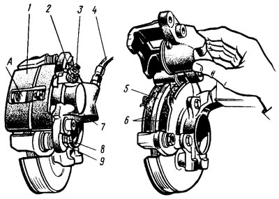
Pic. 121. Replacing brake pads
If during the operation of the car brake fluid was added to the reservoir, then before sinking the piston, a part of the brake fluid is removed from the reservoir to prevent it from pouring out of the reservoir neck. When replacing the pads, check the condition and fit in the sockets of the protective caps of the pistons and covers of the guide pins. If necessary, replace them or ensure the correct fit in the sockets. After replacing the pads, check the condition and fastening of the fitting 2, cap 3 and hose 4.