
Removal and installation
Raise the rear of the car and remove the wheel. Remove the brake drum. After loosening the parking brake cable, disconnect from the lever 10 (see fig. 110) hand drive shoe cable tip, remove the cotter pin, press the finger 9 and remove the lever 10. Remove the guide springs 5 of the shoes, disconnect the top 7 and bottom 3 coupling springs of the shoes and remove the shoes 4.
Having taken measures to prevent leakage of brake fluid from the master cylinder, disconnect the brake fluid supply pipe from the wheel cylinder and plug the inlets of the cylinder and pipe. The wheel cylinder 6 is removed. When replacing the brake shield 11, the bolts of its fastening to the flange of the rear wheel axle are unscrewed.
The installation of parts of the brake mechanism is carried out in reverse order, taking into account the following:
- after installing the pads on the brake shield, make sure that the ends of the pads are correctly positioned in the grooves of the stops of the wheel cylinder pistons and on the base plate;
- before installing the drum, lubricate the landing belt of the hub 2 with graphite grease or LSTs-15.
After assembling the brake mechanisms, press the brake pedal 2-3 times with a force of 40 kgf to set the pistons to the working position. After that, check the ease of rotation of the wheel (light touching of the drum on the pads is allowed). Then adjust the parking brake.
Disassembly and assembly of wheel cylinders
Remove protective caps 2 (see fig. 111), then pressed out (in any direction) from the cylinder body, pistons 4 are assembled with parts for automatic adjustment of the gap between the shoes and the drum. The piston assembly is installed on fixture 67.7820.9525 so that the protrusions of the fixture cover the head of the stop screw 10. With a special screwdriver, turning the piston 4, unscrew the stop screw 10 from the piston. The seal 5 with the support cup 6 and crackers 8 are removed from the screw. The thrust ring 9 and the thrust screw 10 are separated.
The assembly of the automatic device and the cylinder itself is carried out in reverse order, taking into account the following:
- thrust screws of the pistons are tightened with a torque of 0.4-0.7 kgf-m;
- slot A on the thrust rings should be directed vertically upwards, the deviation from the vertical is allowed no more than 30°. This arrangement of the slot ensures the complete removal of air from the wheel brake drive when bleeding the brake;
- when pressing rings, use tool 67.7823.9532;
- to pre-compress the thrust rings, the pistons are pressed into the cylinder body using a special tool in the form of a cylinder with a conical inner hole;
- the force of pressing the piston into the cylinder must be at least 35 kgf. With less effort, replace the thrust ring;
- when pressing the piston into the cylinder, it is necessary to maintain the size of 4.5-4.8 mm and 67 mm (maximum) for free fit of the brake drum; before installing the parts in the cylinder body, they are liberally lubricated with brake fluid.
After assembly, the movement of each piston in the cylinder body is checked. They should move easily within 1.25-1.65 mm. Protective caps 2 are installed last.
Checking details
Wheel cylinders
Check the cleanliness of the working surfaces of the cylinder, pistons and thrust rings. Surfaces must be mirror-like, without visible irregularities, so that fluid leakage and premature wear of seals and pistons do not occur. Defects on the cylinder mirror are eliminated by lapping or grinding. However, an increase in the internal diameter above 20.7 mm is not allowed. Check the condition of the stop screw 10 (see fig. 111), springs 7, support cup 6 and crackers 8. If necessary, replace damaged parts with new ones. Replace seals with 5 new ones. Check the condition of the protective caps 2 and replace them if necessary.
Pads
Carefully check for damage or deformation on the pads. Check the elasticity of the coupling and guide springs of the shoes. If necessary, replace them with new ones. Coupling springs should not have residual deformations when the lower spring is stretched with a force of 14 kgf and the upper 30 kgf (in serviceable springs, the coils are in close contact with each other). Check the cleanliness of the pads, if dirt or traces of grease are found, the pads are thoroughly cleaned with a metal brush and washed with white spirit. In addition, check if there is any leakage of lubricant inside the drum. Faults found are corrected. The pads are replaced with new ones if the thickness of the pads has become less than 1.5 mm. The replacement is carried out simultaneously on both brake mechanisms, i.e. both couples.
Brake drums
Inspect brake drums. If there are deep risks or excessive ovality on the working surface, then the drums are bored on the machine. Then, the drums are also ground on the machine with abrasive fine-grained bars. This increases the durability of the linings and improves braking uniformity and efficiency. An increase in the diameter of the drum after boring and grinding is allowed up to 201 mm. The maximum permissible drum diameter is 201.5 mm. These requirements must be strictly observed, otherwise the strength of the drum is violated, as well as the effectiveness of braking.
Checking wheel cylinders on the stand
Install the cylinder on the stand, attach the pipeline from the pressure gauges to it (pic. 122) and pump the system. Stops 1 are adjusted so that the pistons of the wheel cylinder rest against them. Verify that there is no fluid leakage. Connect a low pressure gauge; slowly rotating the flywheel for controlling the drive cylinder, set the fluid pressure to 0.5 kgf / cm2. Verify that the set pressure is maintained for 5 minutes. Repeat the same test at a pressure of 1 kgf/cm2; 2; 3; 4 and 5 kgf/cm2.
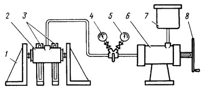
Pic. 122. Scheme for checking the wheel cylinders of the rear brakes: 1 - piston stops; 2 - tested cylinder; 3 - cylinder bracket; 4 - low pressure gauge; 5 - high pressure gauge; 6 - cylinder for creating pressure; 7 - vessel; 8 - flywheel
Then reduce the pressure and connect a high pressure gauge. Adhering to these rules, repeat the test at a pressure of 50 kgf / cm2; 100 and 150 kgf/cm2. Pressure reduction due to liquid leakage through sealing elements, pipeline connections, liquid pumping nozzles or through the pores of the casting is not allowed. Minor (no more than 5 kgf/cm2 within 5 minutes) reduction in pressure, especially at higher pressures, due to shrinkage of seals.