
The design of the suspension creates a negative rolling shoulder, i.e. the point of intersection of the axis of rotation of the wheel with the roadbed lies on the outside relative to the center of the tire contact patch with the road. In combination with a diagonal hydraulic brake separation scheme, this makes the car more stable when braking on slippery roads.
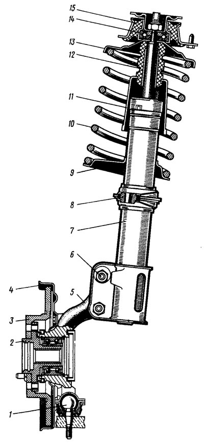
Pic. 81. Telescopic suspension strut assembly with steering knuckle and wheel hub
The main element of the suspension is a telescopic hydraulic shock absorber strut 7 (pic. 81), which combines the functions of guiding and damping suspension devices. The lower part of the telescopic rack is connected to the steering knuckle 5 with two bolts. The upper bolt 6, passing through the oval hole of the rack bracket, has an eccentric belt and a washer. Turning the top bolt changes the camber of the front wheels. In the steering knuckle, the hub 2 of the front wheel is installed on a ball bearing, complete with a brake disc 3, protected by a casing 4. On the telescopic rack are installed: between the support cups 9 and 13 a twisted cylindrical spring 10, a polyurethane foam buffer 12 of the compression stroke with a protective casing 11, as well as the upper support 15 of the rack assembly with the bearing 14. The telescopic rack through the rotary lever 8 is connected to the steering rod. The ball joint 1 serves as the lower support for the rack.
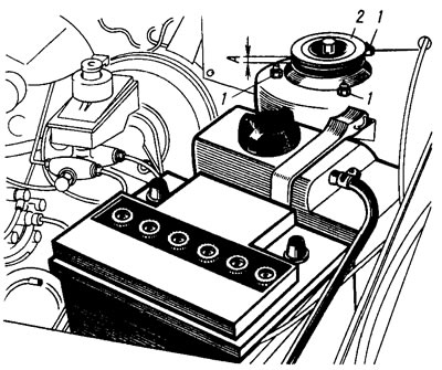
Pic. 82. Fastening the upper suspension support
The top support of the rack is attached with three self-locking nuts 1 (pic. 82) to the mudguard strut. Due to its elasticity, the support provides «rocking» struts during suspension travel and dampens high-frequency vibrations. The bearing built into it allows the rack to turn along with the steered wheels.
Parts of a telescopic hydraulic shock absorber are mounted in the rack body (pic. 83 and 84). In the upper part of the cylinder, a hydraulic recoil stroke buffer is installed, consisting of a plunger 15 and a spring 16. It limits the movement of the rod during the recoil stroke.
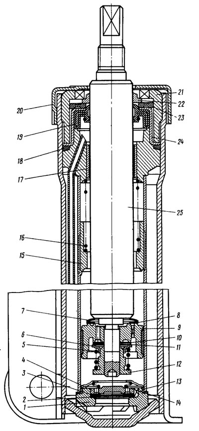
Pic. 83. Telescopic stand: 1 - compression valve body; 2 - compression valve disks; 3 - throttle disk of the compression valve; 4 - compression valve plate; 5 - spring; 6 - recoil valve plate; 7 - bypass valve spring; 8 - bypass valve plate; 9 - piston with ring; 10 - throttle disc of the recoil valve; 11 - recoil valve disks; 12 - recoil valve nut; 13 - clip of the compression valve; 14 - spring; 15 - plunger; 16 - plunger spring; 17 - guide sleeve of the rod with a drain tube; 18 - sealing ring; 19 - stuffing box; 20 - compression buffer support; 21 - housing nut; 22 - protective ring of the rod; 23 - sealing ring of the reservoir; 24 - stuffing box holder; 25 - stock | 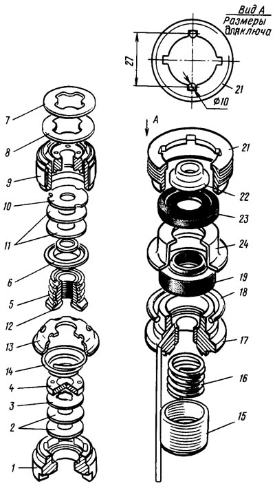
Pic. 84. Details of valves and seals of the telescopic rack. Numerical designations correspond to fig. 83 |
The lower part of the steering knuckle 12 (pic. 85) is connected by a ball joint 13 to the transverse arm 1 of the suspension. Braking and traction forces are perceived by longitudinal extensions 8, which are connected through rubber-metal hinges to transverse levers 1 and to brackets 10. Adjusting washers 9 are installed at the connection points of the extension with the lever and with the bracket, which regulate the angle of longitudinal inclination of the axis of rotation. In the steering knuckle, a double-row closed-type angular contact bearing is installed, on the inner rings of which the hub 2 is installed with an interference fit (see fig. 81). The bearing is tightened with a nut on the shank of the wheel drive outer joint housing and is not adjustable. All front and rear wheel hub nuts are the same and have right hand threads.
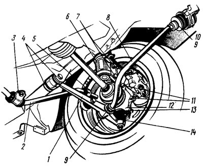
Pic. 85. Suspension of the right front wheel
The anti-roll bar is a 2 bar (see fig. 85), the ends of which are connected through racks 5 with rubber and rubber-metal hinges to the transverse levers 1 of the suspension. Medium (torsion) part of the rod is attached to the body with brackets 3 through rubber cushions.
Possible malfunctions of the front suspension, their causes and methods of elimination are given in Table. 10.