
* Cylindrical mandrel with two bands ∅ 22 and ∅ 33.8 mm.
** Cylindrical mandrel with two bands ∅ 33.8 and ∅ 63.8 mm.
*** Cylindrical mandrel with two bands ∅ 27.8 and ∅ 46 mm; length 167 mm.

Pic. 88. Steering knuckle and front wheel hub parts: 1 - rotary fist; 2 - outer mud-reflecting ring; 3 - hub bearing; 4 - wheel hub; 5 - thrust washer; 6 - nut; 7 - sealing ring; 8 - hub cap; 9 - retaining ring; 10 - internal dirt-reflecting ring
After installing the steering knuckle assembly with the hub, a new or used, but on a different car, nut is installed on the car and tightened to a torque of 23.0-25.2 kgf-m. Unscrew the bolts securing the protective cover 4 (see fig. 81) brake disc and remove it.
By installing the suspension strut in tool 67.7823.9536 (pic. 89), compress the spring 3. Holding the stem with the key 6, unscrew the nut from the stem using the key 5. Remove the limiter 5 (pic. 90), the upper support 6 complete with bearing, the upper support cup 8 of the spring and the buffer 3 of the compression stroke with the casing 2. Having unloaded the spring 9, remove it. Before further disassembly of the rack, check its condition. With vertical stand (stem up) perform several full strokes of tension-compression, after which the rod should move without dips and jams. The rebound force must be greater than the compression force. In this case, there should be no knocks and other extraneous noises. Liquid leakage, deformation and destruction of the rack body, support cup, brackets and rack swing arm are also not allowed. Minor oil stains on the strut housing are not a sign of a malfunction and a basis for replacing or repairing the front suspension strut.
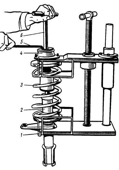
Pic. 89. Dismantling the front suspension strut: 1 - a device for compressing the suspension spring; 2 - telescopic stand; 3 - spring; 4 - upper support of the suspension strut; 5 - key 67.7812.9533; 6 - 67.7812.9535 | 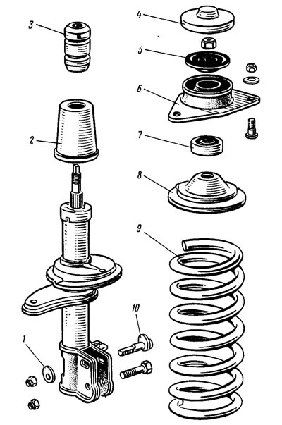
Pic. 90. Elements of the front suspension: 1 - eccentric washer; 2 - protective cover; 3 - compression stroke buffer; 4 - protective cap; 5 - compression stroke limiter; 6 - top support of the rack; 7 - bearing of the upper support; 8 - upper spring cup; 9 - front suspension spring; 10 - adjusting bolt |
A more accurate assessment of the performance of the telescopic rack is carried out on a dyno according to the removed diagram, as indicated in the previous section.
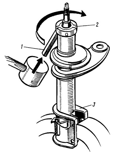
Pic. 91. Removing the support of the compression stroke limiter
If it is necessary to repair the rack, clamp its bracket 3 (pic. 91) in a vise so that his cheeks are perpendicular to the vise jaws. With this fastening, the possibility of deformation of the rack is excluded. Dismantle the rack using tool kit 67.7824.9518, in the following order:
- remove the support of the compression stroke buffer, for which light hammer blows on a flat drift 1 (see fig. 91) tap support 2 from bottom to top and in a circle;
- unscrew the nut 21 with a key 67.7811.9510 (see fig. 83, 84) housings, the working cylinder assembly with the rod and its parts is removed from the rack housing;
- remove the protective ring 22, the gasket 23, the clip 24 assembled with the stuffing box 19 from the rod;
- by pressing on the compression valve plate, the liquid is drained from the cylinder, for which the rod is repeatedly moved by the value of its full stroke without hitting the compression valve so as not to deform its holder;
- having installed the compression valve in a special mandrel, clamped in a vice, slightly shake the cylinder by hand until the compression valve is disconnected from the cylinder;
- having fed down the rod, the piston assembly with the rod is taken out through the lower hole of the cylinder; at the same time, make sure that the fluoroplastic coating of the guide bush is not damaged;
- clamp the rod in a vice by the flats on its shank and unscrew the nut 12 of the recoil valve, after which they remove the parts of the recoil valve, piston 9 and parts of the bypass valve from the rod (it is advisable to first remove the metal in the places of punching, since otherwise, when unscrewing the nut, the thread may be damaged);
- removing the rack housing from the vise, drain the liquid from it;
- carefully knock out the guide sleeve 17 from the working cylinder with a copper hammer or a special drift; at the same time, make sure that there are no nicks on the cylinder;
- remove the spring 16 and the plunger 15 of the hydraulic buffer from the cylinder;
- the compression valve is disassembled, for which the clip 13 is removed, and then the spring 14, the plate 4 and the valve disks 2 and 3 are sequentially removed from the housing.
- The assembly of the front suspension strut is carried out in the reverse order of disassembly, taking into account the following:
- ensure the cleanliness of the workplace and all parts of the rack;
- make sure that the liquid does not have foreign impurities; filter it if necessary;
- make sure that the thread of the recoil valve nut is not damaged when it is unscrewed with a punched stem;
- inspect the stem at the point of punching; if the thread deformation is large and does not allow screwing the recoil valve nut without damaging it, then the stem thread is calibrated with a die;
- the throttle disc of the front strut recoil valve has three grooves along the outer diameter, and the throttle disc of the shock absorber (rear suspension) four;
- the throttle disc of the front suspension strut compression valve has three grooves along the inner diameter, and the throttle disc of the shock absorber has two;
- the recoil valve nut is tightened with a torque of 1.2-1.6 kgf-m, after which it is countered by punching the threaded end of the stem in previously undeformed places; the moment of unscrewing the nut after punching must be at least 2 kgf-m;
- during repair, it is recommended to replace the oil seal and the sealing ring of the rack housing with new ones;
- seal working surface (between sealing lips) fill with SHRUS-4 lubricant in the amount of 0.3-0.4 g;
- pour into the rack body and cylinder (320±5) cm3 liquid MGP-12, in the rear shock absorber (250±5) cm3 MGP-10 liquids;
- the rack housing nut is tightened with the stem fully extended with a wrench 67.7811.9510/11 (tightening torque 12-15 kgf-m, shock absorber 7-9 kgf-m);
- after tightening the nuts, the rack body is minted. The moment of unscrewing the nut after caulking must be at least 30 kgf-m;
- after assembling the compression valve, it is necessary to make sure that the plate and valve disks have free play;
- the compression valve is pressed into the cylinder with a special mandrel *, after which they are once again convinced that the plate and disks have free play;
- a special mandrel is used to install and press the rod guide sleeve into the cylinder; **
- springs of the same class are installed on the front and rear suspensions. Springs along the length under control load are divided into two classes: A and B. Class A springs are marked with yellow paint on the outer side of the middle coils, and class B - green.
* Tubular mandrel with an inner diameter of 33 mm.
** Tubular mandrel with an inner diameter of 37.9 mm.
In exceptional cases, if class A springs are installed on the front suspension, and there are no springs of this class for the rear suspension, it is allowed to install class B springs on the rear suspension. But if class B springs are installed on the front suspension, then only class B springs are installed on the rear suspension.