
The aluminum cover in the plane of contact of the gears must not have ledges. The surface must be flat. With noticeable wear, clamp the cover at points G (pic. 47) and mill surfaces B and C to size (13,5±0,3) mm. The maximum metal removal should not exceed 0.2 mm. The crankshaft seal 1 is replaced with a new one. When pressing the stuffing box, the force is applied as close as possible to the outer diameter of the stuffing box.
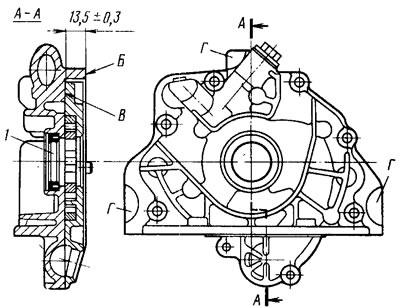
Pic. 47. Mounting points and milling planes of the oil pump cover
The working surfaces of the case must not have scratches. The limiting outer diameter for the driven gear must not exceed 0 75.10 mm (pic. 48). The maximum minimum segment width must be at least 3.40 mm. In case of high wear, the pump housing is replaced with a new one.
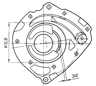
Pic. 48. Limit wear of the oil pump housing
The indicator measures the maximum axial clearances, which should not exceed 0.12 mm for the drive gear; for driven 0.15 mm.
The limiting minimum dimensions of gears are shown in fig. 49. If the gaps and dimensions go beyond the limit values, the gears are replaced with new ones.
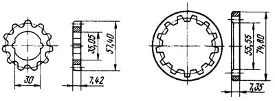
Pic. 49. Limit wear of oil pump gears
They also check whether the elasticity of the pressure reducing valve spring has decreased by comparing the obtained data with the required ones:
- The length of the spring in the free state, mm - 46.5
- Spring loaded length (5,284±0,306) kgf, mm - 31.7
The limiting diameters must be: valve - not less than 11.98 mm; holes for the valve - no more than 12.03 mm.