
The lubrication system consists of an oil pump, an oil filter, a crankcase, an oil filler neck on the cylinder head cover, an oil level indicator in the crankcase, as well as channels in the block and cylinder head. The oil pressure is controlled by the oil pressure gauge on the instrument panel. The pointer sensor is screwed into the oil line hole in the cylinder head, which is connected to the main oil line in the cylinder block. Oil pressure must be at least 4.5 kgf/cm2 at a crankshaft speed of 5600 rpm. The minimum oil pressure must be at least 0.8 kgf/cm2 at 750-800 rpm. When the oil pressure drops below the permissible value, one of the control lamps and the light panel light up in red «STOP» on the instrument cluster.
Oil pump
Gear, with internal gears, is located at the front end of the crankshaft. The pump consists of a cover 9 (pic. 10), housing 1 with suction and discharge cavities and oil receiver 11. Driving 3 and driven 2 gears are installed in the housing. To ensure the necessary clearances between the gears and the housing when the temperature changes, the housing is cast from cast iron, the gears are made from cermet. In the housing, the suction cavity is separated from the discharge cavity by a sickle-shaped protrusion 3 (pic. eleven).
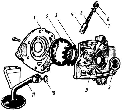
Pic. 10. Oil pump | 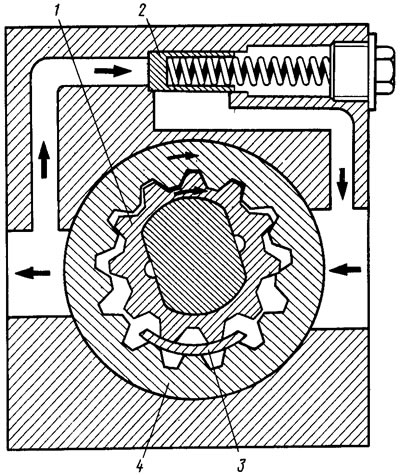
Pic. 11. The scheme of the oil pump |
Presenter 1 (with external teeth) and the driven 4 gears of the pump suck in oil and feed it into the discharge cavity of the pump with the cavities of the teeth. At pressures above 4.5 kgf/cm2 the pressure reducing valve 2 opens and part of the oil is bypassed into the suction cavity of the pump.
Under the cork 6 (see fig. 10) an aluminum ring 7 is placed on the pressure reducing valve. The crankshaft in the cover 9 is sealed with an oil seal 8. The oil receiver 11 is sealed with a rubber ring 10.
Oil filter
Interchangeable with the oil filter of the VAZ-2105 engine. The filter is full-flow, non-separable. A filter element made of special cardboard is installed in the steel housing.
It is not allowed to install large; a-barite oil filter type 2101, as it can touch the right wheel drive shaft.
Crankcase ventilation
Forced, closed, not allowing the release of crankcase gases into the atmosphere. When the engine is running, gases through the exhaust hose 9 (pic. 12) are sucked into the body 8 of the oil separator, the mesh 6 separates the oil. Further, crankcase gases are sucked in through the upper exhaust hose 5 and the crankcase gases outlet pipe 2 and enter the combustion chambers of the engine with the combustible mixture.
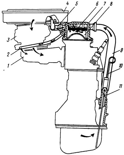
Pic. 12. Crankcase ventilation scheme: 1 - inlet pipeline; 2 - a pipe for removing crankcase gases into the throttle space of the carburetor; 3 - carburetor; 4 - air filter; 5 - upper tension crankcase ventilation hose; 6 - oil separator mesh; 7 - cylinder head cover; 8 - oil separator housing; 9 - lower exhaust hose; 10 - oil level indicator; 11 - fitting