
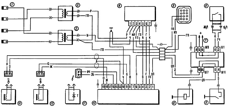
Pic. 112. Scheme of digital ignition system:
1 - spark plugs; 2— ignition coil of the 2nd and 3rd cylinders; 3 - ignition coil of the 1st and 4th cylinders; 4 - switch; 5 diagnostic block; 6 - ignition switch; 7 - mounting block; 8 - carburetor limit switch; 9 - solenoid valve of the carburetor; 10 - controller; 11 - temperature sensor: 12 - angular pulse sensor; 13 - origin sensor.
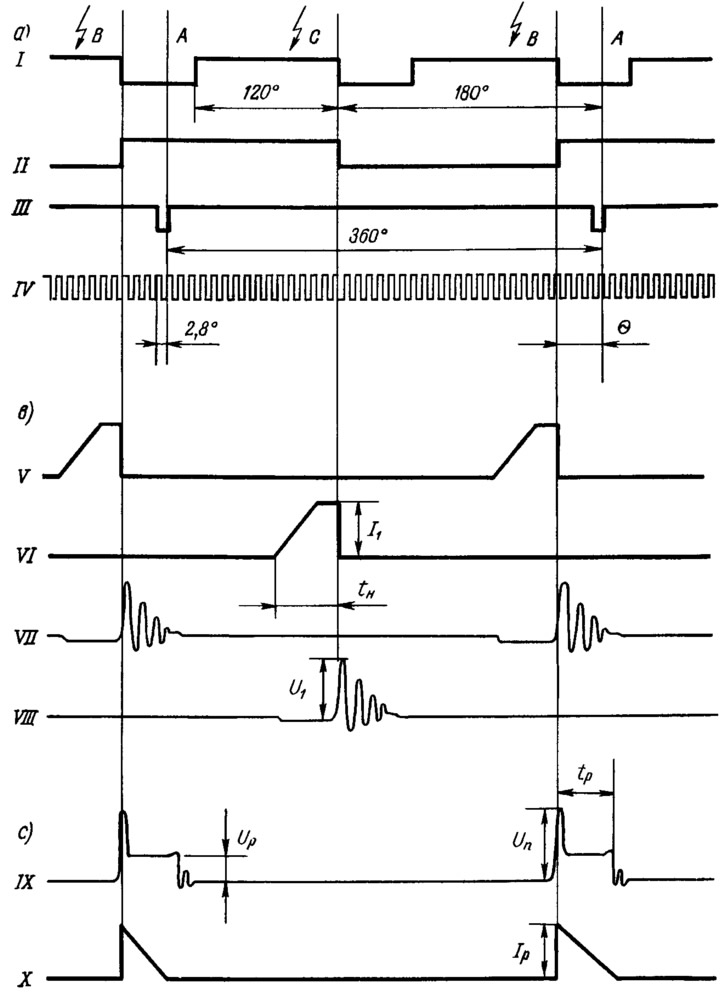
Pic. 113. Oscillograms of voltage and current pulses acting on the controller outputs (A), switch (V) and in the secondary circuit of the ignition coil (With):
I - signal «Ignition timing»; II - signal «Channel selection», III - signal «Reference point»; IV - signal «Angular impulses»; V - current pulses at the output of the 1st channel; VI - current pulses at the output of the 2nd channel; VII - voltage pulses at the output of the 1st channel; VIII - voltage pulses at the output of the 2nd channel; IX - voltage pulses; X - current pulses; A - TDC pistons of the 1st and 4th cylinders; B - the moment of ignition in the 1st and 4th cylinders; C - the moment of ignition in the 2nd and 3rd cylinders; θ - ignition timing; U1 and I1 - current and voltage in the primary winding of the ignition coil; tn is the current accumulation time; UP - spark plug gap breakdown voltage; IR, UR and tR —- current, voltage and discharge time between the electrodes of the candle.
The controller takes into account the information coming from the sensors, from the memory selects the optimal ignition timing 9 for the given conditions and generates pulses «Ignition timing» (NW) And «Channel selection» (VC), shown on oscillograms 1 and 11, fig. 113. The moment of sparking of the SZ signal is determined by the cutoff of the pulse (transition from high to low). The moment of sparking of the VK signal corresponds in the 1st and 4th cylinders to the transition from a low signal level to a high one, and in the 2nd and 3rd cylinders - from a high level to a low one.
The switch smoothly increases the current strength in the primary windings of the ignition coils and, according to the signals from the SZ and VC controller, abruptly interrupts it. As a result, in the primary windings of the ignition coils, current pulses I1 value 8...10 A (waveforms V and VI). In this case, the amplitude of voltage pulses at the output transistors of the switch at the moment of interruption of the current reaches 350...400 V (waveforms VII and VIII). Duration of current pulses tn (or current accumulation time) depends on the speed of the crankshaft and at a supply voltage of 14 V decreases from 8 ms at 750 rpm to 4 ms at 4500 rpm.
As with the contactless ignition system, when the current is interrupted in the primary winding of the ignition coil, a high voltage is induced in the secondary winding. High voltage current close (on the example of coil 2, fig. 112) along the way: the upper high-voltage output of the coil - the candle of the 1st cylinder - «weight» - spark plug of the 4th cylinder - the lower high-voltage output of the ignition coil. In this case, a spark discharge is created simultaneously at two spark plugs: the 1st and 4th cylinders. If one of the cylinders (for example, in the 1st) at this time, the end of the compression stroke occurs and the spark discharge ignites the working mixture, then in the other cylinder (in the 4th) at this time, the release of exhaust gases is completed and the discharge in it does not ignite anything. Thus, in each cylinder during the working cycle (2 turns of the crankshaft) 2 sparks are generated (one is working and the other is single).
The controller controls the solenoid valve 9 of the carburetor depending on the speed of the crankshaft and on the state of the limit switch 8 of the throttle valve. With shutter closed (limit switch closed to «mass») the controller turns off the valve at a speed above 1750 rpm and turns it on again when the speed drops to 1650 rpm. If the carburetor throttle is open (limit switch is not closed with «weight»), the valve does not turn off.
For diagnostic purposes, the following generated signals can be taken from the controller (rectangular pulses). From the plug «5» - NO signal of the encoder, from the plug «7» - PA signal of the control pulse sensor and from the plug «13» SZ ignition timing signal (see oscillograms, respectively, III, IV and I in fig. 113).