
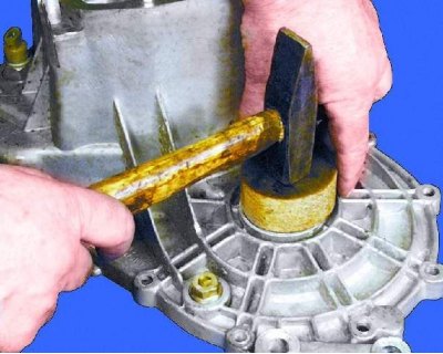
1. Using a suitable mandrel, press the oil seals into the clutch and gearbox housings. Lubricate the sealing lip with Litol-24 grease.
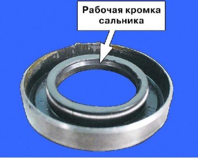
Warning. Press the seals with the working edge inside the box (metal clip out).
2. Press the input and output shaft front bearings into the clutch housing and lubricate them with gear oil.
When assembling the gearbox, lubricate all parts with the same gear oil that you will then pour into the gearbox.
3. Press the differential bearing outer races into the clutch and gearbox housings.
Select the correct thickness shim when replacing one of the following: clutch or transmission housing, differential housing, or differential bearings (see 12.9.4.).
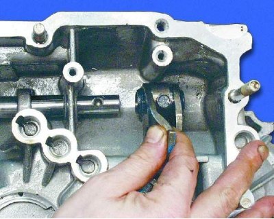
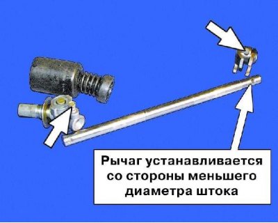
4. Insert the shift rod into the hole in the crankcase. Then install the lever on the stem.
5. Apply TB-1234 glue to the bolt threads (pre-degreased it) and tighten the lever mounting bolt with a torque of 34.0 Nm (3.4 kgf·m).
Note. Bolts of fastening of the lever and the hinge on a rod have different length. Bolt of fastening of the lever of dark color (phosphated) has a length of 19.5 mm, and the hinge bolt is gold-colored (cadmium) - 24 mm.
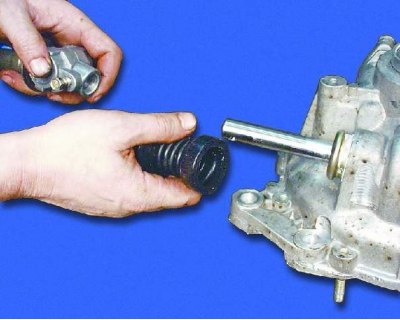
6. Install a protective cover on the stem.
7. Slide the edge of the protective cover around the entire perimeter onto the flanging.
8. Install the pivot onto the stem.
9. Apply TB-1234 glue to the bolt threads (pre-degreased it) and tighten the hinge bolt with a torque of 19.0 Nm (1.9 kgf·m).
10. Slide the edge of the protective cover around the entire perimeter onto the hinge flange.
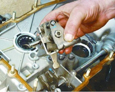
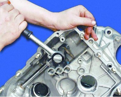
11. Install the gearshift mechanism so that the mechanism lever is between the legs of the stem lever.
12. Wrap three bolts of fastening of the mechanism of a gear change by the moment 5–8,3 Nm (0.5–0.83 kgf·m).
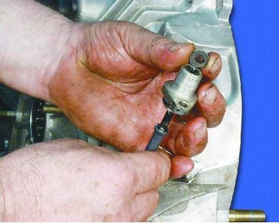
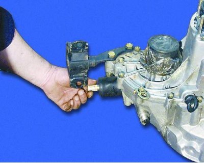
13. Insert the speedometer drive shaft into the housing. Then install the o-ring.
14. Insert the speedometer drive into the clutch housing and tighten the fastening nut to a torque of 4.5–7.2 N·m (0.45–0.72 kgf·m).
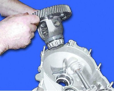
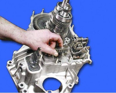
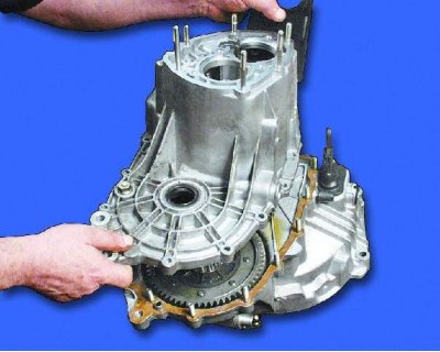
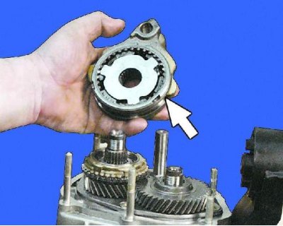
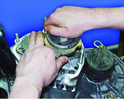
15. Install the differential into the clutch housing.
16. Insert a mandrel into the differential side gear (you can use the old internal CV joint).
Be sure to secure the side gear on the side of the clutch housing so that the gears do not move from their seats, otherwise it may be difficult to install the drive shafts.
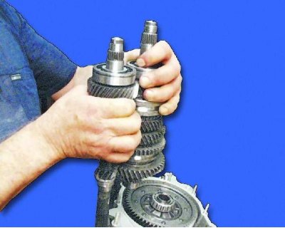
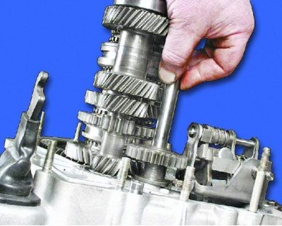
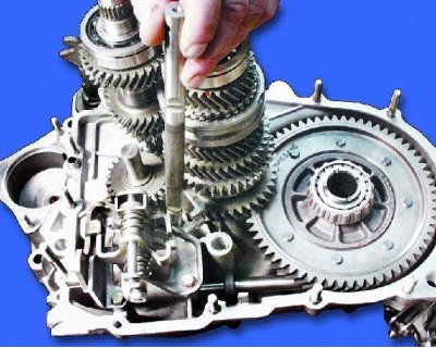
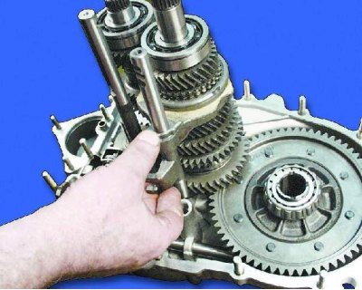
17. Enter the gears of the primary and secondary shafts into engagement.
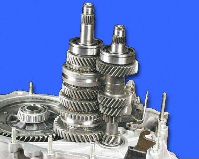
18. In this position, install the shafts in the clutch housing.
19. Lubricate the reverse idler gear bushing with gear oil.
20. Install the reverse idle gear into the clutch housing.
21. Insert the reverse idler shaft.
22. Install the reverse gear lever on the gearshift shaft.
Note. The end of the reverse gear lever must be located in the idler gear groove.
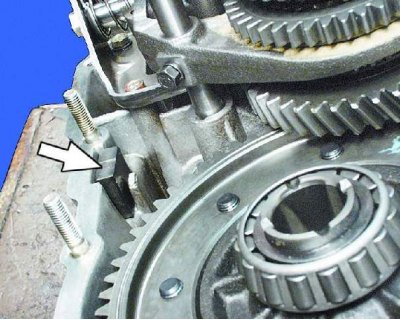
23. Install retaining ring.
Note. If the reverse gear lock ring has play, squeeze the ends of the ring with pliers.
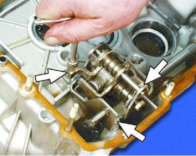
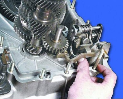
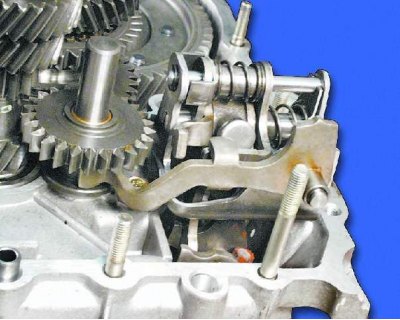
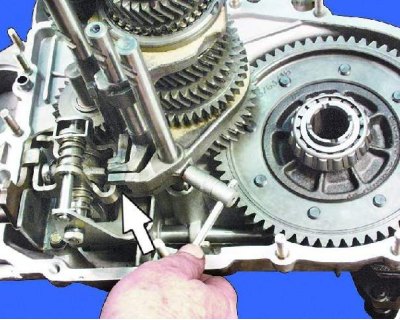
24. Install the 5th shift fork shaft. Turning it around the vertical axis, engage the stem with the locking bracket.
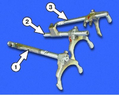
1 - a rod with a fork of inclusion of the 5th transfer
2 – a rod with a fork of inclusion of the 3rd and 4th gears
3 – a rod with a fork of inclusion of the 1st and 2nd transfers
25. Install the 3rd and 4th shift fork on the stem and slide it to the stem head. Insert the fork into the groove of the 3rd and 4th gear synchronizer clutch.
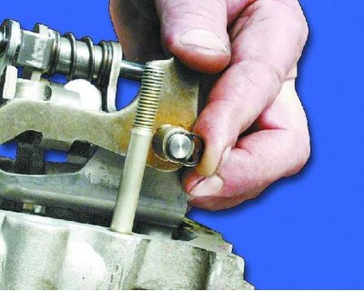
26. Lower the stem into the crankcase bore and rotate it while engaging the stem head with the shift lever. Wrap the fork mounting bolt on the stem with a torque of 12.0–18.0 N·m (1.2–1.8 kgf·m).
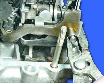
27. Install the shift fork 1st and 2nd gear on the stem and slide it to the stem head. Insert the fork into the groove of the 1st and 2nd gear synchronizer clutch.
28. Lower the rod into the hole in the crankcase, turn it, inserting the head of the fork into engagement with the locking bracket. Wrap the fork mounting bolt on the stem with a torque of 12.0–18.0 N·m (1.2–1.8 kgf·m).
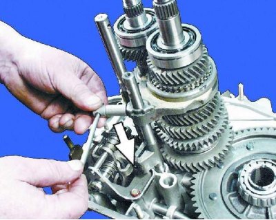
29. Clean the magnet of metal particles and insert it into the crankcase.
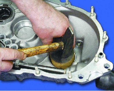
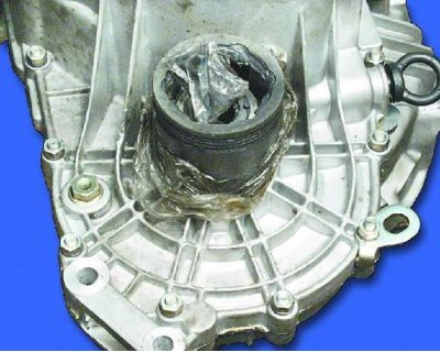
30. Install the seal.
Note. Replace torn and severely compressed gaskets. Before installation, it is recommended to lubricate the gaskets with a thin layer of Litol-24 grease so that they do not move during assembly.
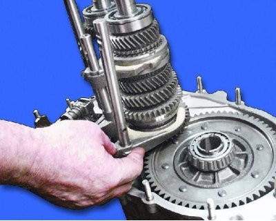
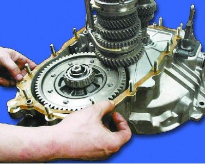
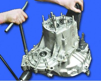
31. Install the gearbox housing to the clutch housing.
32. Lubricate the gearbox parts liberally with gear oil.
33. Torque 16.0 - 26.0 Nm (1.6–2.6 kgf·m) crankcase mounting nuts.
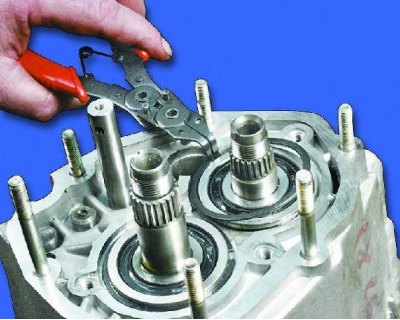
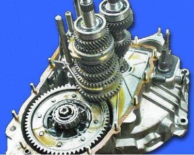
34. Install the circlips on the rear shaft bearings.
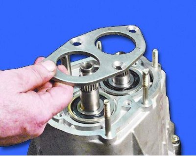
35. Install the bearing mounting plate.
36. Tighten the four plate fixing screws. Then tighten them with an impact screwdriver.
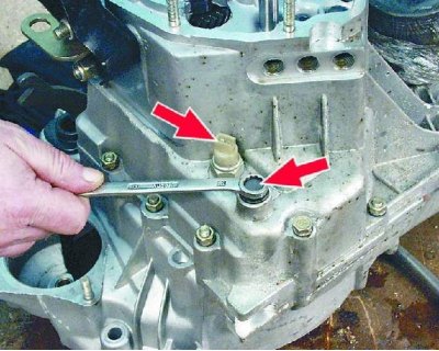
37. Insert the ball with the reverse gear detent spring and tighten the plug with a torque of 29.0–45.0 Nm (2.9–4.5 kgf·m). Screw in the reverse light switch with a torque of 29.0–46.0 Nm (2.9–4.6 kgf·m).
38. Install balls with gear detent springs and tighten the plugs with a torque of 29.0–45.0 Nm (2.9–4.5 kgf·m).
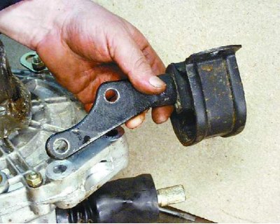
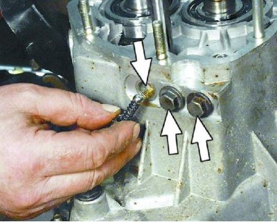
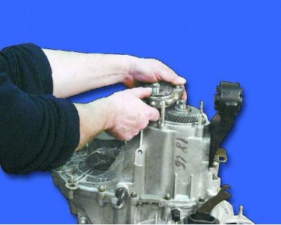
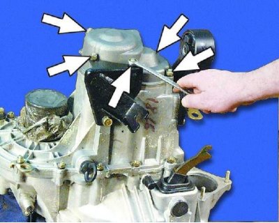
39. Install the power unit rear mount.
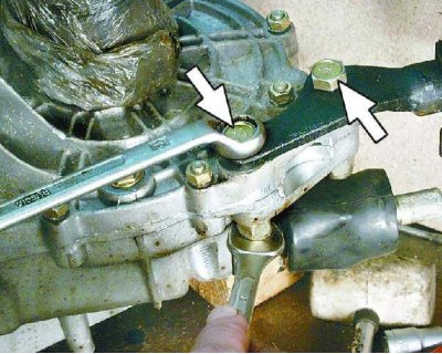
40. Wrap two bolts of fastening of a support the moment 62,0–100,0 Nm (6.2–10.0 kgf·m).
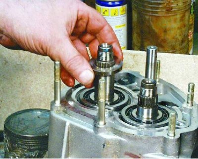
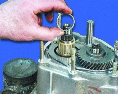
41. Install thrust washer.
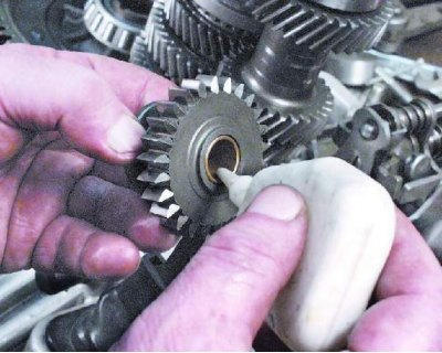
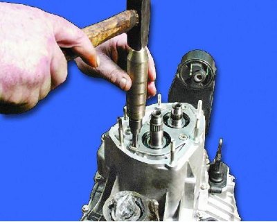
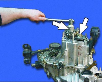
42. Install the 5th gear on the input shaft.
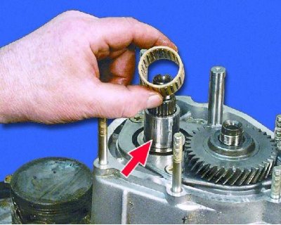
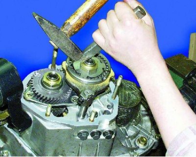
43. Install the sleeve on the secondary shaft until it stops, and then the needle bearing. Lubricate the bearing with gear oil.
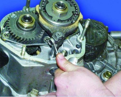
44. Install the distance ring.
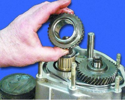
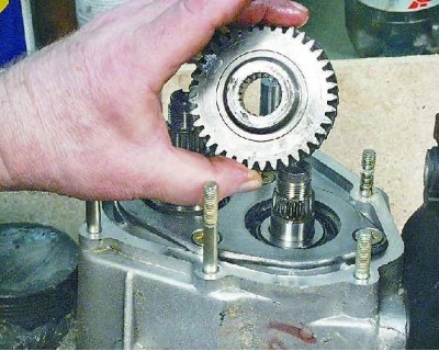
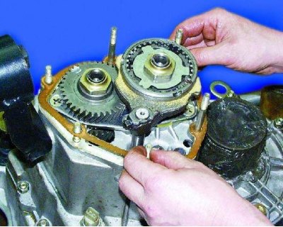
45. Install the 5th gear on the output shaft.
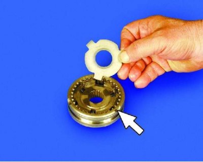
46. Insert the thrust plate into the 5th gear synchronizer from the side of the protrusions on the clutch.
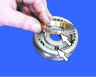
47. On the other side of the synchronizer, insert the blocking ring so that the small protrusions of the ring are located against the grooves with the latches of the synchronizer hub.
48. Insert the inclusion fork into the groove of the synchronizer sleeve.
49. Install the synchronizer on the output shaft and the fork on the rod at the same time, holding the blocking ring from below. Press the synchronizer onto the shaft, applying force to the hub.
50. Engage 3rd or 4th gear.
51. Engage 5th gear by sliding the synchronizer clutch down.
52. Wrap the nuts of the primary and secondary shafts with a torque of 123.0–150.0 Nm (12.3–15.0 kgf·m).
53. Secure the nuts to the shafts by screwing them in.
54. Wrap the fork mounting bolt on the stem with a torque of 12.0–18.0 N·m (1.2–1.8 kgf·m).
55. Install the seal.
56. Install the rear cover with the bracket and tighten the fastening nuts to a torque of 16.0–26.0 Nm (1.6–2.6 kgf·m), as well as the bracket bolt.