
Upper arm
Between the eyes of the lever, install tool 67.7823.9527 on the axle and place the lever on the mandrel A.47045 (pic. 4-10). Using a press punch, press on the axis 1 of the lever until hinge 3 is pressed out of the hole. To press out the second hinge, turn the lever10 over and repeat the operation.
The upper control arm joints are pressed in with special tool 67 7853.9519 (pic. 4-11), clamped in a vise. Install the lever with axle 1 on tool 2, put the hinge on the axle and press it into the lever socket with tool 3 (А74177/1). Then repeat the above operations to press in the second pivot on the other side of the arm.
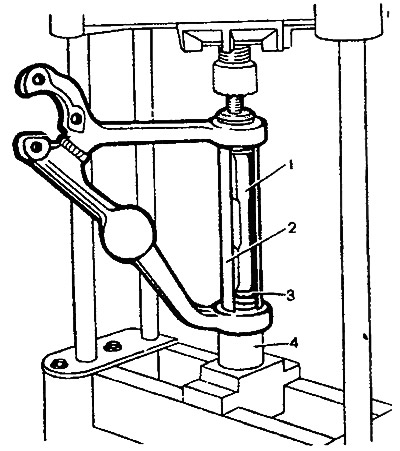
Pic. 4-10. Pressing out the upper arm hinges: 1 - axis of the lever; 2 - fixture 67.7823.9527; 3 - hinge; 4 - mandrel 47045
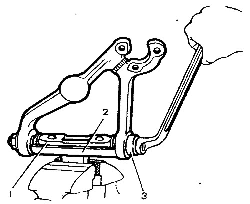
Pic. 4-11. Pressing in upper arm pivots: 1 - axis of the lever; 2 - fixture 67.7853.9519; 3 - fixture А.74177/1
Lower arm
Pressing out and pressing in of the hinge can be carried out both on a press, using tool 67.7823.9526, and with tool 67.7823.9517 (pic. 4-12), which is mounted on the lever so that the head of the screw of the device is directed inward. By tightening the screw of the device, you press the hinge.
To press fit, insert the joint into the lever seat and install special tool 67 7823.9517 (pic. 4-13) complete with cap 3. Turning the screw of the device, press the hinge into the socket of the lever.
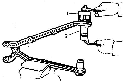
Pic. 4-12. Pressing out the hinges of the lower arm: 1 - fixture 67.7823.9517; 2 - hinge
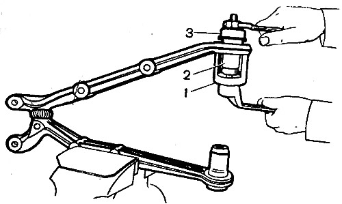
Pic. 4-13. Pressing the lower arm pivots: 1 - fixture; 2 - hinge; 3 - cap