
The deformation of the axles of the lower and upper arms is determined by inspection.
Cross bar deformation front suspension is determined by measuring the distance between the outer surfaces of the cross member brackets in the area of the bolts for fastening the axles of the upper arms. This distance should be 736±1.5 mm.
If the cross member is deformed so that it is impossible to adjust the angles of the wheels with washers in a satisfactory condition of all suspension elements, replace the cross member.
Condition of rubber-metal hinges checked in the following order:
- make sure that there is no deformation of the suspension arms, the axis of the lower arm, the suspension cross member; hang the front wheels of the car;
- measure radial displacement A (pic. 4-2) of the outer sleeve 2 relative to the inner sleeve 6 and the distance B between the thrust washer 5 and the outer end of the outer sleeve 2.
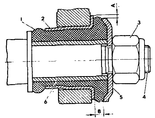
Pic. 4-2. Checking the condition of the rubber-metal hinge of the front suspension arm: 1 - rubber bushing; 2 - outer sleeve; 3 - axle nut, 4 - suspension arm axle; 5 - hinge thrust washer; 6 - inner sleeve
The rubber-metal joints of the upper and lower arms must be replaced:
- with breaks and unilateral «buckling» rubber,
- when cutting and wearing rubber at the ends of the hinges;
- if the radial displacement «A» the outer sleeve relative to the inner one exceeds 2.5 mm;
- if dimension B does not fit within 3-7.5 mm.
If dimension B is outside the specified limits, check that the rubber-metal joint is correctly pressed into the lever socket.
Checking the clearance in the upper ball joints carried out in the following order:
- install the car on a flat horizontal platform with a hard surface;
- raise your right (left) the front of the car and remove the wheel;
- place a wooden block 230 mm high under the lower arm, closer to the ball pin, and lower the car onto it;
- make sure that the swept does not protrude from the sprue hole of the body of the upper ball pin; if necessary, clean it with a file so that there are no measurement errors;
- fasten bracket 4 (pic. 4-3) tool indicator at the upper end of the steering knuckle:
- set the indicator 2 in the center of the sphere of the body 3 of the ball pin with a slight preload, and then align the zero division of the indicator scale with the arrow;
- fasten the forked arm 5 0.7 m long on the upper arm of the front suspension;
- create a vertical load of 196 Nm with a torque wrench 6 (20 kgf·m) (at the end of the forked arm 294 N) first for pressing in, and then for pulling out the ball pin from the hinge body;
- fix the corresponding maximum deviations of the indicator arrow;
- calculate the value of the gap in the upper ball joint by adding the values of the deviation from the zero position;
- the total readings of the indicator should not exceed 0.8 mm.
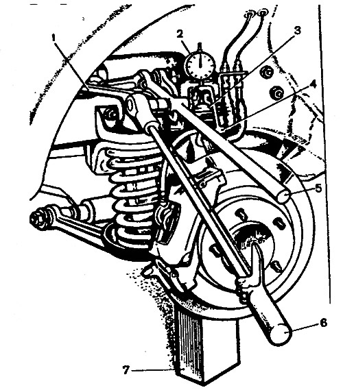
Pic. 4-3. Checking the clearance in the upper ball joints of the suspension on the car: 1 - upper lever; 2 - indicator; 3 - body of the upper ball joint; 4 - indicator mounting bracket; 5 - lever; 6 - torque wrench; 7 - block