
Ball joints
Make sure that the dirt-proof covers of the ball joints are intact; breaks, cracks, delamination of rubber from metal fittings, traces of lubricant leakage are unacceptable.
Check for wear on the running surfaces of the ball joints by manually turning the ball pin. Free movement of the finger or its sticking is unacceptable.
A more accurate check of the condition of the ball joint by the value of the radial and axial clearance is carried out on fixture 02.8701.9502. To do this, install the ball joint 1 (pic. 4-8 A) into the socket of the fixture and tighten it with a screw. Install indicator 2 in the fixture bracket so that the indicator leg rests against the side surface of the hinge body, and the indicator needle is at zero.
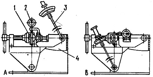
Pic. 4-8. Checking the ball joint on tool 02.8701.9502: 1 - ball joint; 2 - indicator; 3 - torque wrench; 4 - fixture 02.8701.9502; A - scheme for checking the radial clearance; B - scheme for checking the axial clearance
Install the torque wrench 3 in the upper socket of the tool and apply a torque of 196 Nm to it (20 kgf·m) in both directions, use indicator 2 to determine the total radial clearance in the ball joint. If it exceeds 0.7 mm, replace the hinge with a new one.
Similarly, check the axial clearance in the ball joint, after changing its fastening in the fixture, as shown in fig. 4-8 V. Axial clearance in the hinge is allowed no more than 0.7 mm
Suspension spring
Carefully inspect the springs. If deformations are found that may cause a malfunction, replace the springs with new ones.
Compressing the spring three times until the coils touch, check its elastic characteristic according to the control points (pic. 4-9).
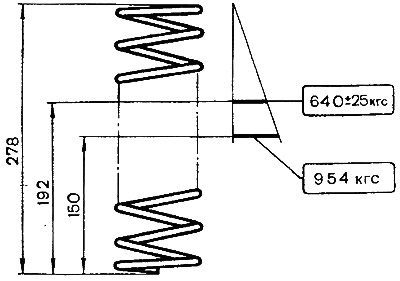
Pic. 4-9. Basic data for checking the front suspension spring
Check the technical condition of the insulating gaskets and replace them if they are damaged.
Stabilizer, suspension arms, steering knuckle
Check if the rod is deformed and if its ends are in the same plane; if the deformation is insignificant, then straighten the bar; in case of significant deformation, replace the rod.
Carefully inspect and make sure that the suspension arms, cross member and steering knuckles are not deformed or cracked.
If there are cracks or deformations, replace the indicated parts.
Suspension cross member
Rolling pin 67.8732.9501 check the geometric parameters of the crossbar. In case of significant deformation of the cross member, when it is impossible to adjust the angles of installation of the front wheels with washers, while all other suspension elements are in satisfactory condition, replace the cross member.
Rubber-metal hinges
Signs of the need to replace rubber-metal joints are described in the chapter «Determining the condition of the front suspension parts».