




Disassemble the carburetor cover. Using a drift, carefully push out the axle 1 (see fig. 9-11) floats 3 from the racks and, without damaging the float tongues, remove them.
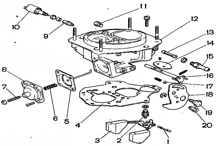
Fig. 9-11. Carburetor cover parts 21073-1107010: 1 - float axis; 2 - needle valve; 3 - float; 4 - gasket; 5 - diaphragm of the starting device with a rod; 6 - spring; 7 - adjusting screw; 8 - starter cover; 9 - idle fuel jet; 10 - electromagnetic shut-off valve; 11 - cork; 12 - carburetor cover; 13 - fuel filter; 14 - air damper 15 - fuel supply pipe; 16 - air damper shaft with lever; 17 - air damper control lever locking ball; 18 - air damper control lever; 19 - lever axis; 20 - air damper drive rod mounting bushing
Remove gasket 4 from the cover, unscrew the seat of needle valve 2, unscrew fuel supply pipe 15 and remove fuel filter 13.
Unscrew the housing of the idle fuel jet with the electromagnetic shut-off valve 10 and remove the jet 9
Unscrew the axle 19, take out the ball 17 with the spring, remove the air damper control lever 18, disconnect the air damper control lever spring. If necessary, unscrew the air damper mounting screws, take out the damper 14 and axle 16.
Disassemble the diaphragm or other starting device by removing cover 8 together with adjusting screw 7. Remove spring 6 and diaphragm 5 with rod.
Disassemble the carburetor body (Fig. 9-12) by performing the following operations.
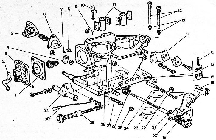
Fig. 9-12. Carburetor body parts 21073-1107010: 1 - accelerator pump diaphragm; 2 - accelerator pump drive lever; 3 - lid; 4 - accelerator pump drive cam; 5 - power mode economizer cover; 6 - economizer diaphragm; 7 - fuel jet economizer; 8 - economizer valve; 9 - accelerator pump check valve; 10 - accelerator pump nozzle with fuel supply valve; 11 - sprayers of the main dosing systems; 12 - main air jets with emulsion tubes; 13 - main fuel jets; 14 - bracket for fastening the air damper drive rod casing; 15 - adjusting screw of the second chamber; 16 - adjusting screw stopper; 17 - Stopper cap; 18 - first chamber throttle valve opening adjusting screw; 19 - first chamber throttle shaft with drive levers; 20 - second chamber locking lever; 21 - locking lever spring; 22 - second chamber throttle valve axis with lever, 23 - first chamber throttle valve; 24 - second chamber throttle valve; 25 - plug for adjusting screw of mixture quality (composition); 26 - return spring of the second chamber throttle actuator lever; 27 - adjusting screw for idle mixture quality (composition); 28 - carburetor body; 29 - idle mixture quantity adjusting screw; 30 - electric wire of the forced idle economizer limit switch; 31 - carburetor heating unit
Remove cover 3 of the accelerator pump with lever 2 and diaphragm 1.
Remove the accelerator pump sprayer 10 and the first and second chamber sprayers 11. Remove sprayer 10 only by the sprayer body.
Unscrew the nut of the first chamber throttle valve axis, remove cam 4 of the accelerator pump drive and washer.
Unscrew the fastening screw, remove the electrical wire 30 from the idle mixture quantity adjusting screw 29 and unscrew the screw 29. Remove the plastic plug 25 with a corkscrew and unscrew the idle mixture quality (composition) adjusting screw 27.
Remove cover 5 of the power mode economizer, diaphragm 6 and spring.
Unscrew the fuel jet 7 of the power mode economizer.
Unscrew the main air jets 12 with emulsion tubes and the main fuel jets 13 of the main metering systems.