




Contents: Clutch ↓ Transfer case ↓ Cardan transmission ↓ Front wheel drive ↓ Rear axle ↓ Front axle ↓
Clutch
The clutch is equipped with a driven disk 21213. This is due to the fact that a greater torque is transmitted through the clutch and, in order to reduce the load on the transmission from uneven engine operation and at the moment of gear shifting, the characteristics of the damper springs have been changed, the shape of the steel disk itself has been changed and other friction linings are used.
Removal and installation, repair of clutch 21213 are performed in the same way as for clutch 2121.
Transfer case
The transfer case of the VAZ-21219 car is no different in its design from the VAZ-2121, but has original protective covers for the transfer case control levers and a different speedometer drive ratio.
Cardan transmission
The cardan transmission of the VAZ-21219 differs from the VAZ-2121 by the intermediate cardan shaft, the design of which allows for the transmission of greater torque and improves the centering of the transfer case and gearbox.
Instead of a cardan joint with a cross on needle bearings, a constant velocity joint is used, the design of which is similar to the design of the outer joint in the front wheel drive.
Removal and installation the intermediate propeller shaft
Install clamp A. 70025 on elastic coupling 3 (Fig. 9-16) and, turning the shaft, unscrew the nuts of the bolts securing the elastic coupling to the flange of the secondary shaft of the gearbox. Remove the transfer case (see subsection "Transfer case" in Section III) assembled with the intermediate cardan shaft. Unscrew the nuts of the studs securing the intermediate shaft joint to the flange of the transfer case drive shaft and remove the intermediate shaft.
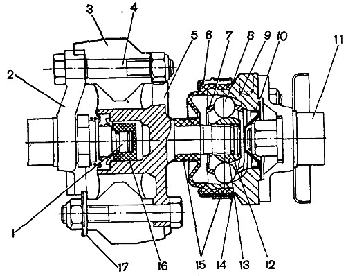
Fig. 9-16. Intermediate cardan shaft: 1 - secondary shaft of the gearbox; 2 - secondary shaft flange; 3 - elastic coupling insert; 4 - flange mounting bolt; 5 - elastic coupling flange; 6 - protective cover; 7 - separator; 8 - ball; 9 - constant velocity joint housing; 10 - plug, 11 - transfer case drive shaft; 12 - retaining ring; 13 - hinge sleeve; 14 - protective cover cap; 15 - clamps; 16 - centering sleeve; 17 - balancing washer
The installation of the intermediate shaft is carried out in the reverse order of removal, taking into account the following:
- before installing the intermediate shaft assembly with the transfer case, apply 2-3 g of SHRUS-4 grease to the inner surface of flange 5;
- when installing the intermediate cardan shaft, ensure that the gearbox and transfer case shafts are centered (see subsection "Installing a transfer case").
Disassembly and assembly of the intermediate cardan shaft
Disconnect the elastic coupling from flange 5 (see fig. 9-16), having noted the number and location of the balancing washers 17 and the coupling itself relative to the flange, so that during assembly they can be installed in their original places.
If the protective cover 6 or casing 14 is damaged, when it is necessary to check the condition of the hinge parts and the quality of the lubrication, having marked the position of the hinge relative to the flange of the elastic coupling, disassemble the hinge using the techniques described in subsection "Front wheel drive".
When assembling the hinge, use the techniques described in the subsection "Front wheel drive". When assembling, apply Longtern-00 grease from the company to the joint "Dow coming" in the amount of 20 cm³.
Front wheel drive
The front wheel drive of the VAZ-21219 uses original seals for the inner joints of the wheel drive. When installing new seals, it is necessary to determine their location (right-left) in the direction of rotation of the drives, which is shown on the seals by arrows.
Rear axle
The VAZ-21219 car is equipped with a gear reducer with a gear ratio of 3.9. For identification, the gear reducer is marked with the number "13" on the flat surface of the crankcase neck.
Front axle
The VAZ-21219 car is equipped with a gear reducer with a gear ratio of 3.9. For identification, the gear reducer is marked with the number "6" on the flat surface of the crankcase neck.